Compared to historical machines, today's systems are both safer and more sophisticated, still they include the same elements:
- A venous reservoir;
- An oxygenator;
- A heat exchanger;
- A pump;
- A filter.
Their purpose is threefold: maintain systemic perfusion, provide gas exchange for O2 and CO2, and regulate temperature. Blood is taken from the systemic venous circulation and returned to the aorta or a large artery once oxygenated; the pulmonary circulation is bypassed. All equipment in direct contact with blood is single-use (tubing, reservoir, oxygenator, etc). The theoretical flow rate provided is 2.0-2.5 L/min/m2 (70 mL/kg/min) (routine: 2.4 L/min/m2). MAP is usually maintained between 60 and 90 mmHg (see Haemodynamics).
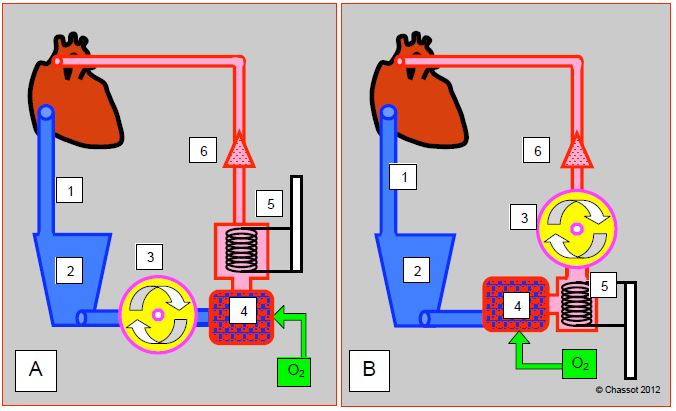
The general set-up of the ECC circuit is well standardized. The main part is made up of 5 elements that follow each other in the following order (Figure 7.2) [2].
Figure 7.2: Schematic representations of an ECC circuit. A: with a membrane oxygenator; has some resistance and is placed after the pump. B: with a bubble oxygenator; has little resistance and is placed between the venous reservoir and the pump. 1: venous drainage cannula. 2: venous reservoir. 3: main pump. 4: Oxygenator. 5: heat exchanger. 6: filter and arterial cannula.
- A large venous cannula leading from the RA to a venous reservoir into which the blood drains by gravity.
- A main pump, usually a roller pump; this pump is placed between the venous reservoir and the membrane oxygenator. On the contrary of bubble oxygenators, where it was placed after the latter.
- An oxygenator, which may be associated with a halogen evaporator (usually isoflurane or sevoflurane) and an air-oxygen flow meter (blender) whose FiO2 regulates PaO2, and the fresh gas flow PaCO2.
- A heat exchanger; coupled to the oxygenator and the venous reservoir carrying out a single use
- An arterial circuit which returns oxygenated blood to the aorta or to a peripheral artery (femoral, right subclavian).
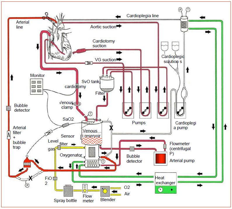
The circuit is completed by several components (Figure 7.3).
Figure 7.3: Synthetic representation of a complete ECC circuit with all its elements. In red: blood circuit. Green: water and heat exchanger circuit. Yellow: fresh gas circuit. Blender: O2/air mixer. X: clamped short circuit. T: temperature measurements (adapted from Gravlee GP, ed. Cardiopulmonary bypass: principles and practice, 2nd edition. Philadelphia: Lippincott, Williams & Wilkins, 2000, p 70).
- An arterial filter that captures particles larger than 40 microns and acts as a bubble trap.
- Two suction circuits: "right" suction for blood drawn from the operating field, "left" suction for blood drawn from the left circulation; these can be supplemented by a cardiotomy suction and drained into a cardiotomy reservoir.
- A cardioplegia circuit with dedicated pump and heat exchanger.
- A pressure control system in the arterial circuit which limits the flow of the master pump set by the perfusionist.
- An on-line venous oxygen saturation (SvO2) and arterial oxygen saturation monitoring system; the SaO2 measured at the outlet of the oxygenator controls the oxygenator, not the patient.
- A venous reservoir level control system that limits the flow rate of the master pump to a preset under the control of the perfusionist.
- A system checking for bubbles in the venous and arterial circuit.
- A system for measuring venous and arterial temperature, respectively at the inlet and outlet of the exchanger block.
Blood flow through this complex tubing system requires anticoagulation, or thrombosis is immediate. Heparin is therefore injected on the basis of 300-400 IU/kg so to achieve an ACT > 450 seconds. Two different materials are used for the tubing: polyvinyl chloride (PVC) and silicones. PVC is transparent and has low particle release but limited tensile and stretch resistance. Silicone better respects the deformability of red blood cells and reduces platelet aggregation, but easily releases particles . Since foreign surfaces and air contact are the main sources of coagulation alterations, hemolysis and post-pump systemic inflammatory syndrome (see Systemic inflammatory syndrome), intense research digs in for possible improvements in ECC circuits. Three main tracks are currently being followed [1].
- Precoated heparin circuits: selective adhesion of plasma proteins to the foreign surface leads to the creation of a molecular film preventing progression of the coagulation cascade. Platelet adhesion is reduced, as is complement activation and coagulation factor adsorption. Although risky, the required ACT can be reduced to 300-350 sec, as long as blood does not stall in the circuit (risk of thrombi constitution). Therefore, circulation in the ECC must be maintained at any time through a bypass between the arterial and venous cannula.
- Biocompatible systems with polymers (poly-2-methoxy-ethyl-acrylate, phosphorylcholine, siloxane) or anti-inflammatory molecules (factor H inhibiting complement C3a, platelet membrane phospholipids). These substances slow down the complement cascade and leukocyte activation.
- Reduction of the tubing length and downsizing of the whole device.
These improvements reduce activation of the coagulatory and inflammatory system, minimise platelets damage and reduce transfusion requirement. They have an impact on postoperative complications in high-risk cases, but have little or no influence for standard procedures in low-risk patients [3,4,5]. Given the increased cost of the circuits, these modifications may not have a favorable cost/benefit ratio for routine use.
The coagulation cascade and systemic inflammatory syndrome are triggered by swollen tissue (surgical wound), foreign surfaces (ECC circuits), and above all by air-blood contact. For these reasons, current technological improvements are aimed at three specific points:
- Suppression of blood-air contact through removal of the open venous system;
- Reduction of the contact surface by downsizing the circuits (see Mini-ECC);
- Washing of the blood aspirated in the operating field (CellSaver™ in closed circuit) before being returned to the circuit.
On the other hand, filling the circuit with the patient's blood (autologous prime) by anterograde (venous cannula) or retrograde (arterial cannula) reduces hemodilution and transfusion requirement (see Priming).
In ECC, hemodynamics is primarily maintained by master pump flow, and is the perfusionist responsibility. After the stress of induction, ECC time requires less concentration for the anesthetist, or even is the opportunity to disappear into his office or the operating theatre cafeteria ! However, the ECC period is a time of close collaboration with the surgeon and the perfusionist. Constant communication between the three is essential for the smooth running of the procedure.
| General diagram of an ECC |
|
An ECC circuit consists of the following components in the direction of blood flow:
- Venous cannula
- Suctions
- Venous reservoir, (with filter), cardiotomy reservoir
- Main pump
- Oxygenator (with O2/air mixer and halogen evaporator)
- Heat exchanger
- Arterial cannula (with filter and bubble trap)
- Cardioplegia circuit
Monitoring: arterial cannula pressure, pump flow, gas flow, SvO2, SaO2 (oxygenator control), venous reservoir level, bubble detectors, arterial and venous temperatures
|
© CHASSOT PG, GRONCHI F, last update December 2019
References
- GUIBAUD JP, OUEDRAOGO N, JANVIER G. Surface treatments of hemocompatible materials for ECC. In: JANVIER G, LEHOT JJ (ed). Circulation extracorporelle: principes et pratique, 2ème édition. Paris, Arnette Groupe Liaison SA, 2004, pp 109-12
- ISETTA C, CADUSSEAU JL. Circuits de circulation extracorporelle: matériels réutilisables, matériels à usage unique. In: JANVIER G, LEHOT JJ (ed). Circulation extracorporelle: principes et pratique, 2ème édition. Paris, Arnette Groupe Liaison SA, 2004, 59-86
- MANGOUSH O, PURKAYASTHA S, HAJ-YAHIA S, et al. Heparin-bonded circuits versus nonheparin-bonded circuits: an evaluation of their effect on clinical outcomes. Eur J Cardiothorac Surg 2007; 31:1058-69
- MURPHY GS, HESSEL EA, GROOM RC. Optimal perfusion during cardiopulmonary bypass: an evidence-based approach. Anesth Analg 2009; 108:1394-417
- SNIECINSKI RM, CHANDLER WL. Activation of the hemostatic system during cardiopulmonary bypass. Anesth Analg 2011; 113:1319-33


