The term oxygenator is a bit restrictive, because the device has three functions: it transfers O2 from external source into the blood, it removes CO2 according to the flow of fresh gas, and it allows the introduction of an anesthetic gas through a vaporizer. There are two types.
- Membrane oxygenators: a thin semi-permeable microporous membrane (0.3-0.8 microns pores, 80-150 microns thickness) with a large total surface area (1.8-2.5 m2) separates blood from Made of polypropylene (tubes), silicone (plates) or Teflon, it is arranged in tubules inside a box (Figure 7.6).
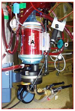
Figure 7.6: The ECC oxygenator. It is usually coupled to the venous reservoir and heat exchanger by the manufacturer. A: body of the oxygenator containing the microfibers for gas exchange. B: venous blood coming from the reservoir via the pump. C: arterial blood leaving the oxygenator. D: gas inlet (with micropore filter). E: heat exchanger. F: pipes for cooling / heating water circulation.
In early systems, the gas mixture flowed through the outside of these microfibers and the blood circulated inside. In today's systems, the blood is on the outside and the fresh gases are inside the microfibers. The blood is only in contact with the gas when the ECC starts, because the micropores are quickly covered with a thin protein layer that separates the two elements [1]; therefore, there is much less trauma to the blood components and proteins. After 6 hours of use, plasma seeps into the micropores and limits exchange. These very fine tubules provide more resistance to blood flow, and membrane oxygenators should be installed after the main pump in the circuit (see Figure 7.2A). Currently, hollow fiber oxygenators account for almost all of the market.
- Bubble oxygenators: technically simple and inexpensive, they involve a bubbling of pure oxygen into the bloodstream followed by a debubbling The smaller and more numerous the bubbles, the greater the surface area of gas-blood contact; debubbling is performed by a polyurethane sponge whose fibers are covered with silicone anti-foam; a filter with a bubble trap completes the system (see Figure 1.2) . The oxygenation capacity is higher than the CO2 removal capacity. This type of oxygenator offers little resistance to flow and can be placed before the main pump (see Figure 7.2B). The major problems with these oxygenators are the embolic risk and the trauma imposed on the blood's components and proteins, resulting in hemolysis, platelet dysfunction, loss of coagulation factors, and a strong inflammatory response. The time limit for their use is 2 hours. They are no longer used.
O2 transfer, distributed by an O2/air blender, is a function of FiO2, surface area and contact time between blood and gas. CO2 removal is a function of the fresh gas flow rate delivered to the system. Care must be taken to ensure that the blood circuit pressure remains higher than the gas circuit pressure. The FiO2 of the oxygenator is set to maintain a PaO2 of about 150 mmHg, and the fresh gas flow to achieve a PaCO2 of 35-40 mmHg (see Hypothermia and Acid-Base Balance). Some systems have automatic feedback of fresh gas flow (O2/air) to the patient's PaO2.
Gases most often used in the vaporizer are isoflurane and sevoflurane. They allow maintenance of anesthesia during ECC (Fi 0.5-2.5%). The arterial vasodilator effect of isoflurane at higher concentrations (3-5%) makes it an effective agent for regulating hypertensive surges commonly experienced during cooling. However, the incorporation of a vaporizer for halogens on the ECC circuit is problematic [2].
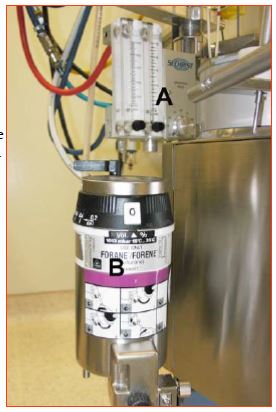
- Halogens in liquid form destroy some of the polypropylene components used in ECC circuits, so they must be handled with great care and the vaporizer must be placed away from the oxygenator and arterial filter, below the ECC circuit (Figure 7.7).
Figure 7.7: The gas blender (A) and the isoflurane vaporizer (B). The vaporizer is located outside and below the ECC circuitry because liquid halogens are corrosive to plastics.
- While it is free through polypropylene membranes, the passage of halogens is blocked by polymethylpentene membranes; the latter are more efficient for the long term and are mainly used in support circuits such as ECMO.
- The outlet of the oxygenator is open air; without an adequate evacuation system, the halogen can pollute the operating room (maximum tolerated quantity: 2 ppm).
- Several manufacturers do not mention the possibility of including a vaporizer in their ECC circuit, which leaves some doubt as to the legality of this setup (not authorized in France and Germany).
Conventional oxygenators have a surface area well in excess of standard requirements, which allows for significant hemodilution to be tolerated, but exposes the blood to a 1-1.5 m2 membrane excess. In mini ECC circuits (see Mini ECC), this waste is eliminated, but the reduced air-blood contact area forces Hb to be maintained at a 10% higher level.
| Oxygenator |
| Current oxygenators are made of tubular porous membranes within which blood circulates, with air inside and blood outside the fibers. Their exchange surface is 1.8-2.5 m2. FiO2 regulates PaO2, as fresh gas flow PaCO2. |
© CHASSOT PG, GRONCHI F, April 2008, last update April 2018
References
- DAVIS RF, THOMPSON J. Technology, pathophysiology and pharmacology of cardiopulmonary bypass. In: THYS DM, et al Eds. Textbook of cardiothoracic anesthesiology. New York, McGraw-Hill Co, 2001,354-75
- NETO CN, LANDONI G, VASSARA L, et al. Use of volatile anesthetics during cardiopulmonary bypass: a systematic review of adverse events. J Cardiothorac Vasc Anesth 2014; 28:84-9


