Prosthetic material causes numerous artefacts because some components absorb ultrasound (invisible) and others reflect it (extremely echogenic). The presence of foreign material creates shadows or gaps in the image (dropout) and causes numerous reverberations. Ultrasound travels slower or faster than in tissue, depending on the type of material; these variations result in distorted (longer or shorter) or displaced (deeper or closer) images of structures. Leaflets and valves normally open and close very quickly. Their move is from one end to the other, from the closed position to the open position. When viewed from the short axis, biological valves appear round when open and as a 3-pointed star when closed; when viewed from the long axis, the ring, two spikes parallel to the flow axis and the valve coaptation zone downstream of the ring can be seen. The double mechanical winglets have a move of 60-70° in the shape of an inverted 'V'. Their function can only be assessed when both winglets are seen to move simultaneously in the same plane (Figure 11.42). Only the transvalvular gradient can provide information: if it is normal for the prosthesis and the haemodynamic situation, it is likely that the valve is opening satisfactorily. On the other hand, the colour flow provides information about the quality of the occlusion: the absence of significant intravalvular leakage ensures that the occlusion is tight. Seeing one winglet from one angle and the other from another should not be reassuring, as the same winglet may well be seen from two different angles.
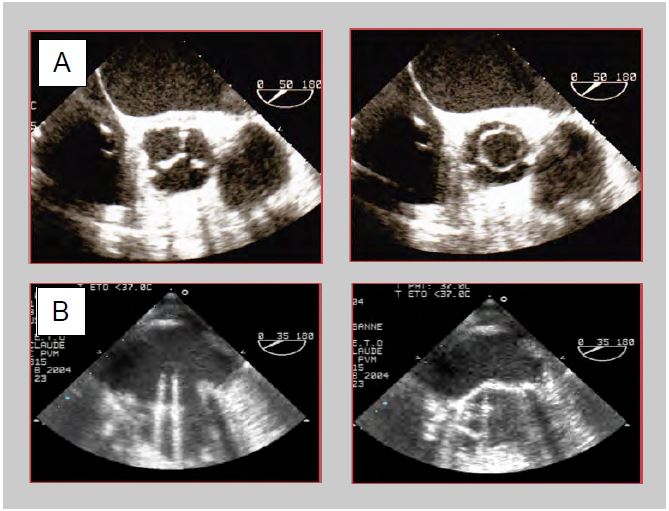
Figure 11.42: TEE images of prosthetic valves. A: Bioprosthesis in aortic position (50° short axis view). Closed in diastole, it presents an image similar to that of a normal valve with its 3 leaflets in anatomical position; in systole it presents a circular opening which is easy to planimeter. B: Mechanical prosthesis in mitral position (30° mid-esophageal view). Open in diastole, the 2 winglets are practically parallel to the blood flow; in systole, the winglets abut the frame and maintain a certain angle with the plane of the annulus.
Double winglet mitral valve prostheses are generally placed in an antianatomical position, with the axis of the winglets perpendicular to the mitral commissure, so that the profile in which the two winglets are seen symmetrically on TEE is between 30 and 70°. This arrangement prevents the winglets from becoming blocked in the subvalvular apparatus and improves ventricular filling by directing flow to the posterolateral region [7]. Examination of the aortic valve is more difficult because the only views along the axis of the prosthesis are deep transgastric at 0-20° or 100-140°; the winglets are aligned with the coronary ostia. Unmounted biological valves and homografts resemble a natural valve except for thickening and/or double contouring of the aortic wall. Double-finned valves have low inertia and open fully even at low flow. Assembled bioprostheses have stiffer cusps, especially those made from bovine or porcine pericardium, and open only partially at low stroke volumes.
The valve must be immobile in relation to the surrounding structures. A rocking motion with each cardiac cycle indicates loosening and dehiscence. However, in the mitral position, preservation of the subvalvular apparatus and leaflet base may allow some mobility of the prosthesis [15]. A periannular cavity without echo suggests dehiscence, abscess or fistula [6]. Elements of the subvalvular apparatus, thrombosis or inflammatory pannus may block a winglet, resulting in asymmetric opening and incomplete closure. Biological valves tend to degenerate after about twelve years; they become fibrotic and calcified, leading to stenosis, or they fragment and tear, leading to leakage. After mitral valve replacement (MVR), fibrin strands are often seen in the LA, appearing as thread-like structures of low echogenicity, a few millimetres long, undulating in the flow around the prosthesis. After aortic valve replacement (AVR), they are sometimes found in the LVOT. These elements are thought to be made of collagen. They can be distinguished from sutures by their stiffness and very high echogenicity. After AVR, the root of the aorta is usually thickened and deformed by a haematoma which subsequently fibrinates, but this cuff may give the impression of a periaortic abscess. This resolves in 3-6 months.
Aspects of Doppler flow
In spectral Doppler, the flow is framed by the two clicks of the prosthesis opening and closing; these are two very dense but very short bands, particularly visible in mechanical prostheses. Colour Doppler flow is accelerated in stents. Its configuration corresponds to the specific profile of each type of valve: swirling flow around the ball in Starr valves, oblique turbulent flow in single-disc valves, accelerated laminar flow in bioprostheses and double-finned valves. In the latter, flow is faster in the slit between the two winglets than in the two lateral openings (see Figure 11.36).
On colour Doppler, prosthetic valves show several types of regurgitation, varying in size and configuration depending on the model [1].
- Although often tight, biological valves have small leaks, usually in the centre but sometimes at the commissures.
- Physiologically, mechanical valves have multiple regurgitant jets, clearly visible on colour Doppler; they are fine and measure 1 cm (aortic prosthesis) to 2 cm (mitral prosthesis) in length. Their origin is clearly within the annulus. These autolavage leaks represent a regurgitation fraction of ≤ 5% and are designed to prevent fibrin deposition on the pyrolocarbon ribs (Figure 11.43) [13].
- Rapid closure of the winglets displaces a certain volume of blood upstream of the prosthesis (closure reflux); this may appear as a brief protosystolic flash; it does not represent a leak.
- Paravalvular leaks are located between the prosthesis and the anatomical ring; they are always pathological (see paravalvular leak below).
Pressure gradients
All prostheses are restrictive compared to normal native valves. Their opening area varies from 1.1 cm2 (aortic bioprosthesis 19) to 3.5 cm2 (mechanical mitral valve 33). As a result, the pressure gradient (ΔP) is significant; the mean gradient varies from 4 mmHg (StJude mitral valve) to 12-20 mmHg (aortic bioprosthesis) (Tables 11.7, 11.8 and 11.9) [8,9,12,15]. For the same size, the gradients are in ascending order: autografts < homografts < stentless bioprostheses < mechanical valves < attached bioprostheses. It is easy to overestimate the gradient of a prosthesis and therefore underestimate its surface area due to several phenomena [15].
- Doppler calculates ΔP from Vmax, which corresponds to the narrowest point of the flow (vena contracta); this zone is generally very short (1-3 mm) and the pressure rises rapidly in the downstream chamber (Figure 11.44). The exaggerated gradient measured by Doppler tends to underestimate the true opening area in small prostheses and large aortas. For this reason, the mean gradient is a better criterion than the maximum gradient [14].
- The geometry of the prosthesis induces a phenomenon known as pressure recovery: the pressure drops as the velocity increases in the constricted zone, but the kinetic energy is converted back into pressure as soon as the flow slows beyond the constriction [11]. With a small aortic stent graft (19-21 mm), this phenomenon can represent a reduction of up to 20% compared to the pressure gradient measured on echo [2]. As the loss of kinetic energy in the vortices reduces the extent of pressure recovery, the phenomenon is less pronounced when the aorta is much larger than the prosthesis because there are more vortices.
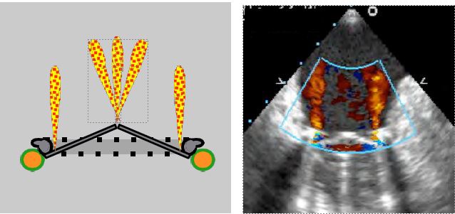
Figure 11.43: Autolavage intravalvular leaks. This type of leak inside the prosthesis ring is normal. It varies according to the type of mechanical valve, both in number and size, but the insufficiency is always minimal (regurgitation fraction ≤ 5%). In bileaflet valves, the peripheral jets are slightly concentric, while the jets on the pivots are in a bouquet. They are always fine and never show a zone of concentric acceleration on the ventricular side (90° 2-cavity TEE image of a St Jude valve in the mitral position).
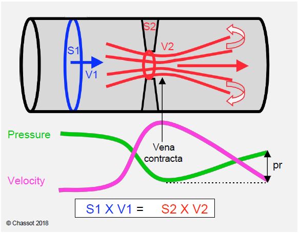
Figure 11.44: Illustration of the equation of continuity and the phenomenon of pressure recovery. The continuity equation expresses the law of conservation of kinetic energy; as velocity increases, pressure decreases and vice versa. Vmax is reached just distal to the constriction (called the vena contracta because of the contraction of the flow); this is where the pressure is lowest and the pressure gradient is greatest. The pressure is recovered distally (pr, pressure recovery) as the velocity decreases and the duct widens; the recovery is not complete because of load loss due to frictional forces and the formation of vortices [14].
- The gradient is measured with the Doppler axis in the centre of the valve in biological prostheses, but in one of the two wide lateral orifices in double-finned valves, because it is increased by 40% in the central part.
- After AVR for stenosis, the velocity in the LV plenum is often greater than 1.5 m/s due to LVH and the decrease in ventricular afterload. It is therefore essential to use the modified Bernoulli equation ΔP = 4 · (V2VAo - V2LVOT ) and not its simplified version (ΔP = 4 · V2 ). Omitting the subtraction of Vmax in the LVOT leads to an overestimation of the gradient by 9 to 30 mmHg. On the spectral display, the flow of the dynamic stenosis in the LVOT shows a dagger shape and a telesystolic peak velocity, whereas that of the fixed stenosis in the prosthesis shows a protosystolic peak velocity (see Figure 11.115).
- For the calculation of the continuity equation, the measurement of the diameter of the LVOT is difficult because of the brightness and shadows of the prosthesis; in addition, TEE views only allow the measurement of the small diameter of the LVOT, which is oval rather than circular in cross-section. This leads to an underestimation of the valve area.
- On leaving bypass, flow is accelerated due to catecholaminergic stimulation and the transient increase in stroke volume (transfusion, high flow, haemodilution, extrasystole). On the other hand, low pressure in the aortic root (vasoplegia, intra-aortic balloon pump, ascending aortic aneurysm) increases the gradient of an aortic prosthesis by reducing the downstream pressure; in IABP, this difference is of the order of 30-40 mmHg. In these situations, the artificially accelerated velocity through the prosthesis tends to underestimate its true surface area.
- When different levels of examination give different velocity values, the window giving the highest velocities is the most reliable.
At the aortic level, interference from variations in flow and stroke volume can be eliminated using the ratio (R) between the integral of velocities (VTI) in the LVOT and the VTI across the valve:
R = VTILVOT / VTIVAo.
This ratio, also known as the patency index, quantifies the acceleration of flow at the level of the stent where the diameter is narrower (see Figure 11.30). Normally it is around 0.5 - 0.7; it must remain above 0.4 or the stent is stenosing; a value < 0.25 represents a tight stenosis [15]. It can also be used to differentiate between an increase in gradient due to a large stroke volume (hypervolaemia, high flow, sepsis, anaemia, AI) and that due to stenosis, as in the former case it remains normal; in fact, the increase in velocity is identical in the LVOT and through the stent.
In general, the mean gradient is more relevant than the maximum gradient because it is less dependent on instantaneous haemodynamic conditions [4]. In addition, the mean gradient calculated by echocardiography correlates well with the angiographic mean gradient, whereas the instantaneous maximum Doppler gradient is generally larger than the maximum peak-to-peak gradient at catheterisation (see Figure 11.28) [11].
The detection of an excessive gradient across a prosthesis (ΔP mean > 15-20 mmHg in the aortic position, ΔP mean > 5-7 mmHg in the mitral position) does not necessarily mean that the prosthesis is malfunctioning. There is some evidence to clarify the situation [9].
- Ensure that the gradient is measured in the side ports of double valve prostheses, as the velocity through the central slot is 40-50% higher.
- Measure Vmax in the LVOT in the aortic position and calculate the ratio VLVOT /VVAo ; if it is > 0.4, the valve function is normal.
- Assess whether there is a mismatch between the size of the prosthesis and the patient's body surface area; if the surface area of the prosthesis is < 0.85 cm /m2 in the aortic position or < 1.2 cm /m2 in the mitral position, the size of the valve is insufficient for the patient's cardiac output (see Complications of prostheses, Patient-prosthesis mismatch).
- Assess the extent of any valvular regurgitation that increases systolic or diastolic volume.
- Compare echocardiographic measurements with haemodynamic measurements: is there aortic arterial hypotension (IABP), increased stroke volume (Swan-Ganz, PiCCO), excess catecholamines β (cardiac output)?
- As a last resort, measure the peak-to-peak gradient between the LV and the ascending aorta in AVR or between the LV and the LA in MVR.
| Prosthetic valves |
| Prosthetic materials absorb ultrasound (shadow zones) or reflect it (reverberation).
Wing movement (mechanical prostheses)
- The 2 leaflets must be visible on the same image
- Mitral valve: mid-esophageal view 40-80°.
- Aortic valve: 0° or 120° transgastric view
Cusp motion (biological prostheses)
- Mitral valve: 4-cavity 0° view - 2-cavity 90° view
- Aortic valve: 40° short axis view
Mechanical prostheses show normal autolavage leaks (FR 5%); biological prostheses show optional leaks of variable location
Prostheses are restrictive compared to a normal native valve, in ascending order of pressure gradient (ΔP): autografts < homografts < stentless bioprostheses < mechanical valves < attached bioprostheses (ΔPmax 5 - 40 mmHg).
The pressure gradient increases in the following cases: assembled bioprosthesis, small size, aortic position, high cardiac output, hypervolaemia, vasoplegia, IABP, etc.
In the aortic position, ΔP must be calculated using the full Bernoulli equation: ΔP = 4 · (V2VAo - V2LVOT ). After AVR, the ratio VTILVOT/VTIVAo must be > 0.4; a lower value indicates stenosis.
Pressure recovery is an important phenomenon in mechanical valves.
|
- The opening and closing of the winglets and cusps is incomplete when assisted by the ECC.
- Hypovolaemia, haemodilution and low cardiac output reduce velocities and gradients; the true surface area is overestimated by the continuity equation.
- Hypervolemia and inotropic stimulation increase velocities and gradients; the continuity equation underestimates surface area.
- Intra-aortic balloon pump (IABP) greatly increases the maximum gradient across the aortic valve because of the very low pressure in the ascending aorta during protosystole; to a lesser extent, vasoplegia has the same effect.
- Tachycardia limits flow through the atrioventricular valves by shortening diastole.
- Arrhythmias interfere with prosthesis evaluation. Atrial fibrillation requires measurements to be averaged over several cardiac cycles, the duration of which corresponds to a frequency of 60-80 beats/min.
Evaluation of the prosthesis is based on 2D imaging, colour Doppler and gradient calculations. The two-dimensional views highlight the opening/closing of the prosthesis.
- Double winglet mechanical prosthesis: simultaneous movement of the 2 winglets on the same image, in a 30-80° mid-esophageal view (mitral prosthesis) or a 0° and 120° transgastric view (aortic prosthesis). Simultaneous viewing of the 2 winglets is the only two-dimensional proof that the prosthesis is functioning correctly. Seeing only one leaflet in two different planes, even if the orientation of the winglet is different, does not rule out the possibility that the same winglet is actually seen twice and the other remains invisible. This is confirmed by the colour flow (double passage through the two large orifices) and the gradient calculation. In the mitral position, it is always possible to find a plane where the 2 winglets appear simultaneously. In the aortic position, the image depends on the orientation of the prosthesis; it may not be possible to see both winglets.
- Bioprosthesis: Movement of cusps in 0-90° retrocardiac view (mitral bioprosthesis) or 40° short-axis view (aortic bioprosthesis); measurement of orifice area by 40° short-axis planimetry (aortic bioprosthesis).
- It is normal to see a cuff around the aortic root after AVR (haematoma, thrombus, suture).
- Presence of sutures, look for thrombus and fibrin filaments.
Several complications can be detected immediately by TEE.
- Winglet blockage: lack of movement and flow over half of the prosthesis, excessive gradient; usually caused by the subvalvular apparatus (mitral position) or the LVOT musculature (aortic position). This blockage can be corrected by rotating the prosthesis in its ring, but this requires a return to ECC.
- In the case of a bioprosthesis in the mitral position, the anterior part of the valve may partially obstruct the LVOT; measurement of Vmax in the LVOT (risk of stenosis).
- After MVR:
- Lateral fixation points of the prosthesis may damage the circumflex artery and lead to lateral akinesia. This is because the CX pathway in the left atrioventricular trine is only a few millimetres from the mitral annulus, and lateral fixation points can easily penetrate and occlude the vessel.
- Fixation points at the level of the trine can cause restriction of the non-coronary or left coronary cusp of the aortic valve and induce or aggravate insufficiency (AI).
- The most serious surgical complication that can occur after mitral valve surgery is a tear in the annulus and base of the LV, most commonly during reoperation. Reconstruction is extremely risky and mortality is very high.
- After AVR :
- Flow control in the common trunk and right coronary artery.
- Control of the mitral valve: attachment points of the aortic prosthesis at the level of the trine can pull on the anterior winglet and trigger an MI or aggravate a pre-existing leak. Decalcification of the mitral valve angle may result in a tear at the root of the anterior mitral winglet.
- Septal myectomy in the LVOT, often associated with AVR for aortic stenosis and significant LVH, may be excessive and cross the subaortic septum from side to side, leading to iatrogenic VSD. The coloured flow shows a systolo-diastolic vortex passage between the LV and RV.
- Complete AV block due to lesion of the His bundle in the part adjacent to the membranous septum below the non-coronary cusp.
- Paravalvular leak, CMO effect, patient-prosthesis mismatch: see below and under prosthesis complications.
The coloured flow is necessary to guide the positioning of the pulsed/continuous Doppler in the anterograde and retrograde flow. It shows regurgitation.
- Autolavage leaks in mechanical prostheses; their number and size depend on the model; they are intravalvular and small.
- Residual leaks in the bioprosthesis (central and/or at the commissures).
- Paravalvular leaks outside the annulus; these are always pathological.
- Mitral leak due to retraction of the anterior leaflet by the posterior sutures of an aortic prosthesis.
- Aortic leak due to retraction of the non-coronary or left coronary cusp by the sutures used to implant a mitral valve prosthesis.
- Subaortic VSD flow after excessive LVOT myectomy.
The occurrence of MI after AVR may be related to several different phenomena.
- Mesosystolic reopening of the mitral valve in dynamic sub aortic stenosis (SAM); although significant, this MI is brief and does not last throughout systole: it is meso-telesystolic. It is often the first sign to diagnose the HOCM effect (see Complications of heart valve prostheses).
- Retraction of the anterior leaflet by prosthesis anchoring points; the proximity of the aortic and mitral annuli at the trine means that slightly wide points in this area exert traction on the anterior leaflet and may prevent it from closing properly.
- LV dysfunction; MI is a common sequela of acute LV dilatation or ischaemia.
- Persistence of a pre-bypass MI, whether organic (calcific disease, degeneration, age-related changes) or functional (mitral annular calcification, LV dysfunction or dilatation). In most cases, the removal of the obstacle to ejection by the AVR reduces LV wall stress to such an extent that the MI is less significant than preoperatively.
The gradients vary according to the type of prosthesis, but are always greater than those of a normal native valve. They vary with the size of the valve. In simplified terms, the following benchmarks can be used for mean gradients and maximum velocities (which vary with size) (see Table 11.7, Table 11.8 and Table 11.9 for details) [8,9,12,15].
- Mitral position:
- Two-wire mechanical valve ΔPmoy 3-5 mmHg Vmax 1.2 - 1.6 m/s
- Attached bioprosthesis ΔPmoy 6 mmHg Vmax 1.5 - 1.8 m/s
- In aortic position :
- Bioprosthesis without frame ΔPmoy 4-8 mmHg Vmax 1.5 - 1.8 m/s
- Two-wire mechanical valve ΔPmoy 6-15 mmHg Vmax 2.0 - 2.5 m/s
- Fixed bioprosthesis ΔPmoy 12-20 mmHg Vmax 2.5 - 3.0 m/s
In the aortic position, it is essential to calculate the gradient using Bernoulli's equation, which takes into account the velocity in the outflow chamber (ΔP = 4 · (V2VAo - V2LVOT ), as this is often well above 1.5 m/s under the haemodynamic conditions at the pump outlet: concentric LVH, hypovolaemia, catecholaminergic stimulation and reduced afterload due to removal of the stenosis. Dynamic subaortic stenosis is defined by an LVOT Vmax > 2.5 m/s; it alone induces a ΔPmax > 25 mmHg. The ratio between VTI in the LVOT and through the valve (R = VTILVOT / VTIVAo) is useful for assessing the degree of acceleration generated by the prosthesis.
However, several phenomena can cause a falsely high transprosthetic gradient across an aortic prosthesis [10].
- Transient episode of high stroke volume: hypervolaemia, too rapid transfusion from the ECC venous reservoir, haemodilution.
- Pressure recovery: kinetic energy is converted back into pressure beyond the zone of maximum acceleration, where pressure is minimal; as echocardiography measures pressure precisely at maximum velocity, it tends to overestimate the true gradient (see Figure 11.44).
- Dynamic subaortic stenosis (HOCM effect): the removal of the obstacle to ejection may cause a hypertrophied ventricle to collapse in systole, because its cavity is naturally small and the outflow tract is very muscular; the anterior leaflet of the mitral valve is displaced towards the LVOT and is sucked in to the point of partially blocking the flow. This is systolic anterior motion (SAM), a phenomenon similar to obstructive cardiomyopathy (Figure 11.45). This systolic narrowing of the outflow tract creates a dynamic obstruction that can represent a gradient of 25-40 mmHg upstream of the prosthesis (see Complications of Prostheses, Dynamic Subaortic Stenosis).
- Even in the absence of muscular stenosis, LV outflow velocities may exceed 1.5 m/s due to significant sympathetic stimulation and transient hypervolemia. In this case, Bernoulli's equation must be corrected to account for Vmax in the LVOT: ΔP = 4 (V22 - V12 ), where V2 is Vmax through the prosthesis and V1 is Vmax in the LVOT. The gradient generated in the LVOT is then subtracted from the total gradient to give the prosthesis specific gradient (see Fig. 11.121).
- The presence of intra-aortic balloon pump (IABP) significantly reduces the pressure in the ascending aorta at the start of systole as the balloon deflates; this results in an exaggerated gradient between the LV and the aorta; the gradient should be measured during a brief cessation of IABP. Significant dilatation of the ascending aorta has the same effect.
- Patient-prosthesis mismatch: an orifice area < 0.85 cm /m2 creates an excessive gradient (see Complications of prostheses, Patient-prosthesis mismatch).
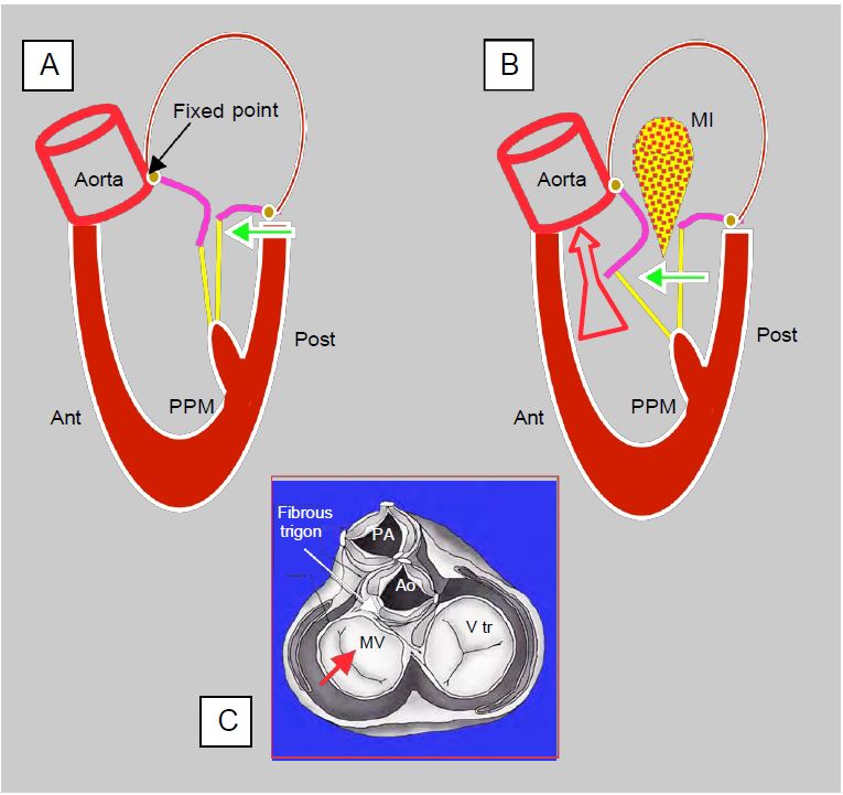
Figure 11.45: Dynamic obstruction of the LVOT after mitral valve repair. A: A restrictive annulus and/or excessive height of the posterior leaflet (PL) (anterior to posterior leaflet ratio < 1.3) advances the posterior wall and projects the coaptation point towards the LVOT (green arrow). In the protocole, coaptation takes place on the body of the anterior leaflet (AL), the distal part of which is in the LV and not against the PL. B: In mesosystole, intraventricular pressure pushes the AL towards the LVOT; during ejection it is sucked in by the Venturi effect and blocks the LVOT (SAM: systolic anterior motion). The aortic flow drops suddenly and the reopening of the mitral valve causes meso-tesystolic insufficiency (MI). C: When the LV is narrowed, only the posterior wall can move anteriorly (red arrow) because the base of the anterior leaflet is attached to the fibrous trine, which is a fixed point because it is the skeleton and mechanical centre of the heart.
Paravalvular leak
The paravalvular leak (PVL) is located outside the prosthetic ring. It is always pathological, but its impact varies according to its size.
- Small leaks (grade ≤ I) are not significant; they generally disappear rapidly with protamine or within a few days with fibrin deposition and endothelialisation.
- Small leaks are inevitable when the valve annulus is heavily calcified and congruence with the prosthetic annulus is impossible.
- In the tricuspid region, the surgeon may not fix the prosthesis on the septal side to avoid damaging the His bundle, leaving an extra-annular orifice.
- Moderate to severe leaks (50% of cases) should be corrected whenever possible as they tend to worsen over time and cause significant haemolysis.
- Tolerance of PVL is higher for aortic leaks than for mitral leaks because the velocity is lower and the risk of haemolysis is lower in the aortic position. Tolerance is very high for tricuspid PVL where the velocity is low.
Large paravalvular leaks show characteristic signs (Figure 11.46).
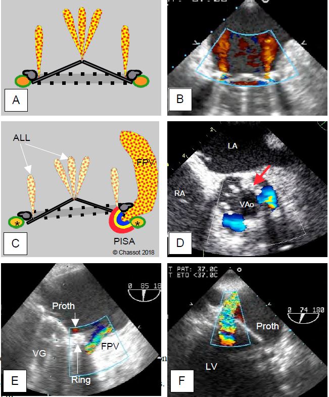
Figure 11.46: Paravalvular leak. A and B: Normal autolavage leaks from a bivalvular mechanical prosthesis in the mitral position; fine, intravalvular, parallel or bouquet jets, no zone of acceleration C: Diagram showing that the paravalvular leak is located between the annulus of the prosthesis and the anatomical annulus of the valve (*), whereas the autolavage leaks (ALL) are within the valve. A large AVL has a zone of concentric acceleration (PISA) on the ventricular side. D: Short-axis aortic PVL; two leaks around the prosthetic annulus (arrow) at 3 and 7 o'clock; persistence of flow in diastole through the paravalvular orifices. E: Anterior mitral PVL; a small physiological leak is visible inside the prosthetic annulus (arrow). F: Posterior mitral PVL.
- Free passage localised outside the annulus on 2D imaging (inconstant sign).
- PISA on the anterior surface.
- Passage around the annulus visible on colour Doppler.
- Vena contracta ≥ 0.3 cm.
- Large downstream vortex flow, often eccentric.
- Mitral prosthesis: search for PVL around the prosthesis by placing the colour window at the mitro-aortic angle in 4-cavity view and rotating the sensor angle from 0° to 180° while keeping the window on the left side of the prosthesis on the screen. Then place the window on the other side of the valve and rotate back 180° to 0°, keeping the window on the right edge of the prosthesis on the screen.
- Aortic prosthesis: look for PVL in long-axis mid-oesophagus 120° and transgastric 0° - 120°; locate it in short-axis 40° at the periphery of the annulus (diastolic vortex).
- 3D imaging with reconstruction of an "en-face" view of the valve is used to measure the extent of the paravalvular leak(s). A severe leak represents > 20% of the valve circumference (moderate leak: 10-20%, mild leak: < 10%) (Figure 11.47) [15].
Video: major posterior paravalvular leak swirling in the LA, together with a small normal intravalvular leak.
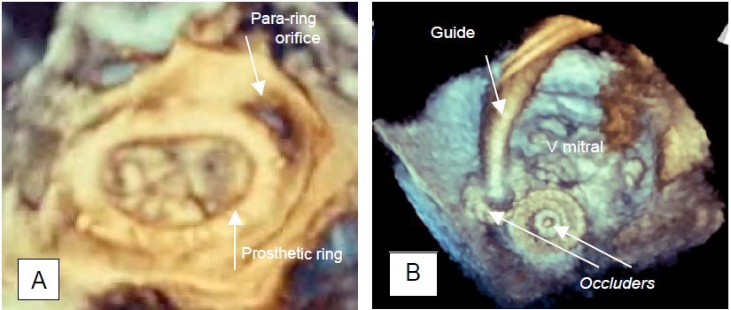
Figure 11.47: Paravalvular leak (PVL). A: Paravalvular regurgitant orifice outside a Carpentier annulus after mitral valve repair (3D TEE view from the LA). B: Occlusion of a paravalvular leak by a device used for AIC closure. Two devices are in place (occluders), one is still suspended from its guide (3D TEE view from the LA).
Locating a paravalvular leak on two-dimensional imaging is not always easy, but is facilitated by a very systematic approach.
- After MVR: search around the prosthesis; the 4-cavity 0°, bicommissural 60°, 2-cavity 90° and long-axis 120-140° views define 4 planes visualising 8 quadrants of the annulus (Figure 26.65); the position of the left atrial appendage, the tricuspid valve and the aortic valve are additional landmarks.
- After AVR: The 40° short-axis view of the aortic prosthesis shows where the leak is in diastole around the circumference of the prosthetic annulus (Figure 11.46D).
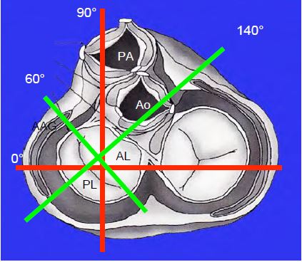
Figure 26.65: The 4 standard transesophageal planes allow the definition of 8 quadrants of the mitral annulus, ensuring efficient localisation of a paravalvular leak; the left atrial appendage (LAA), the aortic valve and the tricuspid valve are additional landmarks. The orthogonal planes of the body (0° and 90°) are shown in red and the orthogonal planes of the mitral valve are shown in green (60° and 120-140°).
Localizing leak is very important, as it can be difficult for the surgeon to identify the orifice in the operating field when the heart is flaccid, and the leak is usually located under the prosthetic annulus. The decision to return to ECC to close the paravalvular orifice is not based on the TEE image alone, but on a series of contingencies: the valve incriminated, the condition of the annulus, the surgical feasibility of the repair, the clinical risk of 2nd ECC, etc... . If surgery is too risky, a paravalvular leak can be subsequently reduced with an occluder device used to close AICs (Amplatzer™ type occluder).
Examination of an aortic prosthesis
A normal aortic prosthesis gives an image of mild stenosis with a Vmax > 2 m/s and an average pressure gradient of 6 to 20 mmHg depending on the type and size of the prosthesis (see above). The spectral image of the continuous Doppler flow has a triangular shape with an early peak (acceleration time < 80 msec) and an VTILVOT/VTIVAo ratio ≥ 0.4. The opening area calculated by the continuity equation (SAo = (SLVOT · VTILVOT ) / VTIAo ) is generally ≥ 1.5 cm2 , but must be adapted to the type of valve in question. If the prosthesis is stenotic, Vmax exceeds 3-4 m/s and the mean gradient exceeds 30 mmHg. The flow takes on a rounded shape with a mesosystolic peak velocity (acceleration time > 100 msec) (Figure 11.48). An VTILVOT/VTIVAo < 0.25 and an orifice area < 1 cm2 indicate an unacceptably tight stenosis [15]. As these measurements may lead to reintervention with ECC, it is important to consider LV function. Left-sided failure results in a longer acceleration time but a lower Vmax and a reduced gradient, which may indicate that the prosthesis has a sufficient opening area. In contrast, a hyperdynamic LV will result in excess velocity and gradient, but with a short acceleration time and an VTILVOT ) / VTIAo > 0.4.
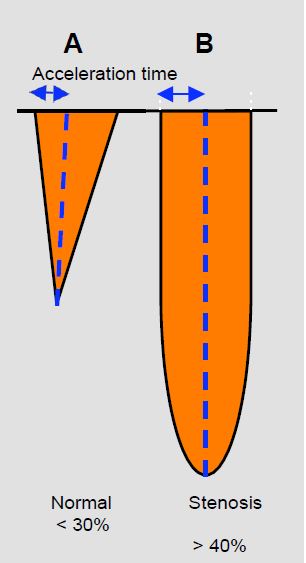
Figure 11.48: Spectral images of continuous Doppler flow in aortic stenosis (transgastric position). A: Mild aortic stenosis flow with short acceleration time (< 30% of ejection time), triangular shape and protosystolic peak. B: Tight aortic stenosis flow with rounded flow, long acceleration time (> 40% of ejection time) and mesosystolic peak.
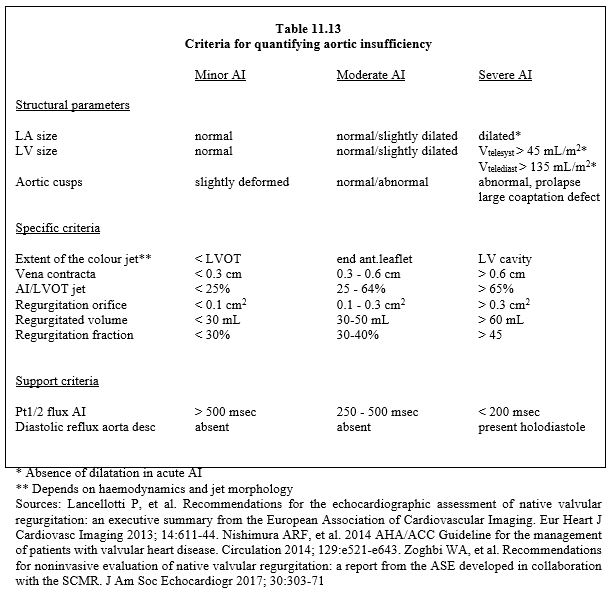
The presence of a swirling diastolic jet in the LVOT indicates the likelihood of regurgitation. Quantification of residual regurgitation is not straightforward in the long-axis or short-axis mid-esophageal views because of the shadow cast by the prosthesis frame on the outflow tract and leaflets. Although the valve is further away from the sensor, deep transgastric views at 0° or long-axis views at 120° are more suitable for measuring the diameter of the vena contracta (criteria identical to those for a native valve leak, see Table 11.13). In addition to assessing the size of the insufficiency, the question of its intra- or para-valvular origin is crucial, but not always easy to resolve. In the former, the leak is usually central, whereas in the latter it is more eccentric, but prolapse of a poorly fitting stentless prosthesis can cause an eccentric leak even if it is intravalvular. The presence of a zone of concentric acceleration (PISA) anterior to the prosthesis indicates a significant leak.
Examination of a mitral prosthesis
A normal mitral prosthesis has a Vmax ≤ 1.9 m/s (mechanical valve) to ≤ 2.4 m/s (bioprosthesis) and a mean gradient ≤ 5 mmHg. The half-pressure time (Pt1/2) is only applicable to stenotic areas (≤ 1.5 cm2 ) and does not allow the calculation of the opening area of prostheses. The continuity equation is preferable, using the stroke volume in the LVOT as a reference, provided there is no aortic or mitral regurgitation: MVS = (SLVOT · VTILVOT ) / VTIM ). The ratio between the integral velocities through the mitral prosthesis and the integral velocities in the LVOT (VTIM / VTILVOT ) is the inverse of the ratio used for the aortic valve, but fulfils the same function: to measure mitral stenosis independently of haemodynamic conditions; it is usually < 2.2 (≥ 2.5 in severe stenosis) [4]. All these measurements require a normal haemodynamic status, adequate blood volume and a stable heart rate.
| TEE examination after prosthetic valve implantation |
| Normal haemodynamic conditions (blood pressure > 80 mmHg, satisfactory blood volume and ventricular function)
Movement of the 2 leaflets or 3 cusps visible in the same plane
Physiological leakage (fine, intravalvular jets, expansion < 2 cm)
Calculation of gradients (ΔPmax and ΔPmean)
Mitral position
- Lateral wall contraction
- Pulmonary vein flow
- New aortic leak
- Patient-prosthesis mismatch if S < 1.2 cm2 /m2 ; if severe mismatch (S < 0.9 cm2 /m2 ): Immediate return to ECC
In aortic position
- Measure Vmax in LVOT and look for SAM (risk of dynamic stenosis)
- Measurement of Vmax in the ventricular cavity
- Patient-prosthesis mismatch if S < 0.85 cm2 /m2 ; in case of severe mismatch (S < 0.65 cm2 /m2 ) Immediate return to ECC
- New mitral leak
- Coronary flow (CT and RCA)
- If LVOT myectomy/myotomy: search for SVD
Significant paravalvular leak (outside the valve annulus)
- Visible passage around the valve (mitral prosthesis: 0-180° scan in retroposition) aortic prosthesis: short axis 40°)
- Variable jet shape and direction (≥ 2-3 cm)
- PISA upstream
- Beam width ≥ 0.3 cm
Dynamic obstruction of the LVOT by forward displacement of the anterior mitral leaflet is common under certain circumstances:
- Removal of an obstruction due to aortic stenosis (AVR)
- Restrictive mitral regurgitation (high reduction ring)
- Reduced LV cavity (hypovolaemia, severe concentric LVH)
- Reduced afterload (vasoplegia, IABP)
- Excessive catecholamine stimulation β
|
References
- BACH DS. Transesophageal echocardiographic (TEE) evaluation of prosthetic valves. Cardiol Clin 2000; 18:751-64
- BAX JJ, DELGADO V. Advanced imaging in valvular heart disease. Nat Rev Cardiol 2017; 14:209-23
- BURSTOW DJ, NISHIMURA RA, BAILEY KR, et al. Continuous wave Doppler echocardiographic measurement of prosthetic valve gradients. A simultaneous Doppler-catheter correlative study. Circulation 1989; 80:504-11
- FERNANDES V, OLMOS L. NAGUEH SF, et al. Peak early diastolic velocity rather than pressure half-time is the best index of mechanical prosthetic mitral valve function. Am J Cardiol 2002; 89:704-10
- FRANK M, GANZONI G, STARCK C, et al. Lack of accessible data on prosthetic heart valves. Int J Cardiovasc Imaging 2016; 32:439-47
- KARCHMER AW LONGWORTH DL. Infections of intracardiac devices. Infect Dis Clin North Am 2002; 16:477-89
- MAHMOOD F, MATYAL R, MAHMOOD F, et al. Intraoperative echocardiographic assessment of prosthetic valve: a practical approach. J Cardiothorac Vasc Anesth 2018; 32:823-37
- OH JK, SEWARD JB, TAJIK AJ. The echo manual. 3rd edition. Philadelphia, Lippincott Williams & Wilkins, 2006, 189-242
- PIBAROT P, DUMESNIL JG. Prosthetic heart valves: selection of the optimal prosthesis and long-term management. Circulation 2009; 119:1034-48
- RAJANI R, MUKHERJEE D, CHAMBERS JB. Doppler echocardiography in normally-functioning replacement aortic valve: a review of 129 studies. J Hesart Valve Dis 2007; 16:519-35
- STEWART SF, NAST EP, ARABIA FA, et al. Errors in pressure gradient measurement by continuous wave Doppler ultrasound: type, size and age effects in bioprosthetic aortic valves. J Am Coll Cardiol 1991; 18:769-79
- VAHANIAN A, ALFIERI O, ANDREOTTI F, et al. Guidelines on the management of valvular heart disease (version 2012). The Joint Task Force on the Management of Valvular Heart Disease of the European Society of Cardiology (ESC) and the European Association for Cardio-Thoracic Surgery (EACTS). Eur Heart J 2012; 33:2451-96
- ZABALGOITIA M. Echocardiographic assessment of prosthetic heart valves. Curr Probl Cardiol 2000; 25:157-66
- ZOGHBI WA, ADAMS D, BONOW RO, et al. Recommendations for noninvasive evaluation of native valvular regurgitation: a report from the ASE developed in collaboration with the SCMR. J Am Soc Echocardiogr 2017; 30:303-71
- ZOGHBI WA, CHAMBERS JB, DUMESNIL JG, et al. Recommendations for evaluation of prosthetic valves with echocardiography and Doppler ultrasound. J Am Soc Echocradiogr 2009; 22:975-1014