Venous cannulae
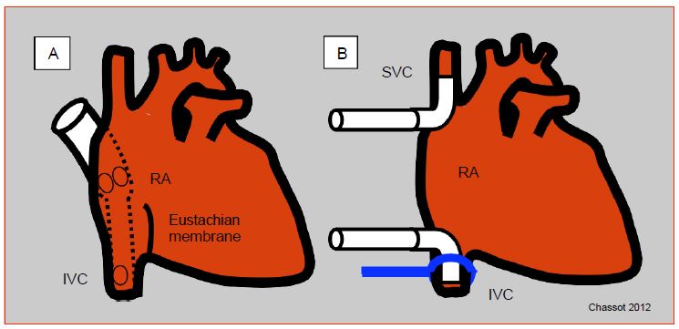
Venous blood is usually drained from the RA through one or two large cannulas (36F - 51F) connected to a half-inch tube. The single-cannula system is simpler, faster, and requires only a single incision in the atrium, usually at the atrial appendage; the cannula has ports located in the RA and extends into a smaller tube that is introduced into the inferior vena cava (IVC). This system is very sensitive to manipulation of the heart and does not provide a seal for venous drainage; it allows partial bypass in which some pulmonary circulation persists, but it is not suitable when the right atrium must be opened or the heart displaced [3]. In this case, the two vena cava are cannulated separately from two incisions in the atrium; the cannulas are sealed by tightening a lace around each vena cava; which leaves the coronary sinus flow to be evacuated from the RA (except in the case of a left superior vena cava: see Chapter 15 Abnormal venous returns). When the heart is stopped and the cardioplegia has stopped flowing, the coronary sinus flow is zero. Alternatively, right-angled metal cannulas can be used to cannulate the vena cava directly away from the RA, as it is performed during heart transplantation (Figure 7.4).
Figure 7.4: Venous cannulation. A: Single cannula; introduced through the right atrium, the cannula extends into the inferior vena cava (IVC); it has openings in the RA and IVC; the former drains blood from the superior vena cava and coronary sinus. B: Bicanulation; each vena cava is cannulated separately; a drainage system recovers blood from the coronary sinus into the RA. The lace to seal the vena cava connection is shown at the level of the IVC. Cannulas can be introduced into the vena cava from the RA or more distally through an incision on the vessel.
Drainage of venous blood into the reservoir occurs by gravity. This siphon effect depends on several factors.
- The height between the patient and the reservoir, normally 30-70 cm; venous return can be enhanced by raising the operating table.
- The volume of the RA; hypovolemia and venodilation by nitroglycerin or propofol decrease venous return to the atrium.
- Venous cannula positioning and heart displacement during surgical maneuvers; double cannulation provides better return when the heart is tilted to open the left atrium (mitral surgery).
- Collapse of the RA walls around the cannula when the flow to the reservoir is higher than the return through the vena cava; this is a common occurrence when using a booster pump on the venous return.
- Air in the cannulas can lead to obstruction by an air lock that forms in the upper part of a tubing loop.
In addition to poor venous return, several complications can occur with venous cannulation.
- Arrhythmias during manipulation of the RA (frequent transition to AF).
- Blockage of the IVC cannula by the Eustachian membrane.
- Obstruction of the IVC or suprahepatic veins; hepatic stasis ensues.
- Obstruction of the SVC; watch the face carefully during bicannulation; if the superior vena cava is obstructed, facial edema, conjunctival and palpebral edema, and cyanosis of the superior vena cava territory are quickly observed. This can be assessed by measuring the pressure in the lateral arm of the introducer. A persistent increase in the pressure in the SVC can lead to cerebral edema and a dangerous drop in cerebral perfusion pressure (CPP = MAP - Pvjug) detectable by a drop in ScO2.
- Passage of the cannula into the LA through a patent foramen ovale (PFO).
- Passage of air through a central catheter with leaky inlets.
- Passage of air through an unknown patent foramen ovale (PFO) in case of opening of the left cavities (e.g. mitral valve operation).
- Persistent venous return through a left superior vena cava, present in 2-10% of congenital cases (see Figure 15.7).
When a single atrial cannula is used, the CVP reading in the RA (distal end of the central catheter or Swan-Ganz RA tract) reflects filling of the patient; its increase also reflects a hindrance to return to the ECC reservoir. During bicaval cannulation, the RA is empty, its pressure is zero. The only measurable pressure is the one read in the lateral arm of the introducer which reflects the jugular venous pressure. However, the pressure proximal to the inferior vena cava cannula cannot be monitored.
When a peripheral vein such as the femoral vein is cannulated, the flow rate is rarely sufficient to ensure the venous return necessary for the patient's calculated flow rate based on an index of 2.4 L/min/m2, even if the cannula goes all the way up to the iliac vein. This cannulation only allows circulatory assistance. A second cannula in the atrium, a long cannula from the femoral vein to the RA, and/or the interposition of a suctioned pump on the venous circuit are required to achieve optimal flow. New, long, mesh cannulas (Smartcanula™) that do not collapse and drain the venous outlets along their entire length allow for desired flow without a pump. Cannula insertion from the femoral into the RA is guided by transesophageal echocardiography (TEE); the TEE first visualizes the guidewire, which should ascend into the SCV and avoid the fossa ovale; this guidewire passes easily into the LA if the foramen ovale is patent. The cannula should then be positioned in the middle of the RA, with its tip in the SVC outlet (see Figure 7.34).
Venous reservoir
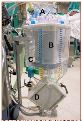
The venous reservoir is the compliance chamber that allows arterial flow to be maintained constant despite variations in venous return (Figure 7.5).
Figure 7.5: The ECC venous reservoir. A: venous blood drainage circuit (blue plugs) from the patient (right atrium, suctioned). B: venous filter. C: reservoir itself partially filled with priming solution. D: oxygenator coupled to the heat exchanger. E: pipes for water circulation with the cooling / heating tank. It can be seen that the blood is largely in contact with the air in this type of tank.
1 to 3 liters of blood can be transferred to the reservoir at the start of ECC in case of a patient with congestive heart failure, on the contrary during heart manipulation, for example, venous return can decrease drastically and force the perfusionist to use the reservoir volume to maintain flow. The level of the reservoir must remain above a certain threshold below which the system no longer has a preload reserve and risks letting air into the arterial part of the circuit. At a flow rate of 4 L/min, a 500 mL reserve only allows 7.5 seconds of flow before the reservoir is empty [2]. The perfusionist must therefore pay constant attention to the reservoir level. The reservoir is equipped with an alarm system that immediately informs when the minimum level is reached and shuts off the pump before it draws air into the aorta. Some reservoirs are flexible and collapse when they are emptied, which excludes air embolization; they limit the contact of blood with air, but their use is tricky. The venous circuit includes an adjustable clamp so to modify the return flow.
Suctions from the surgical field are drained into a reservoir called the cardiotomy reservoir, which has the unique ability to filter and defoam the blood and then to eliminate the risk of embolizing suctioned particles or air bubbles. The cardiotomy reservoir has a debulking chamber containing a sponge impregnated with an anti-foaming substance, a storage chamber, and a 30-40 micron filter. In most systems, the venous reservoir and the cradiotomy reservoir are one and the same.
The major disadvantage of the reservoir is that it provides a large contact surface between air and blood. This interface is one of the major causes of complement activation, platelet aggregation and triggers the inflammatory syndrome. These phenomena are much less pronounced with flexible reservoirs.
Assisted venous drainage
When the size of the circuit and cannulas is reduced to limit the priming volume and contact with foreign surfaces, the diameter of the venous cannulas becomes restrictive and siphoning by gravity is no longer sufficient to ensure correct drainage of the RA. Indeed, Poiseuille's law specifies that flow is equal to pressure divided by resistance, and that resistance is the product of fluid viscosity (ρ), tube length, and the inverse of radius to the power of 4: Q = P - r4 / ρ - L. As the tube diameter decreases, a pump system must be added to the venous circuit to improve flow. Two assist systems are used.
- Suction (vacuum-assisted venous drainage): adjustable vacuum system applied to the venous reservoir, sucking blood into it from the RA; the reservoir shell must be rigid.
- Pump (kinetically assisted venous drainage): centrifugal or roller pump mounted on the venous circuit; its flow rate is constantly adapted to the volume of the return and the suction effect.
Although very effective in ensuring good venous return, these systems present several potential problems [1].
- Additional pumping to be monitored by the perfusionist, who must also ensure that the pressure is never positive in the venous circuit or negative in the arterial circuit.
- Air suctioned from the bursae around the RA or vena cava; the pump will crush these bubbles and turn them into microbubbles escaping the filters placed on the venous and arterial lines, with a risk of arterial embolisms for the patient.
- Additional shear stress on the red blood cells leading to more hemolysis.
- Possible blockage of the return flow by suctioned vascular walls in the cannula ports;
- Risk of oxygenator vacuum and retrograde flow to the reservoir within the machine; a pop-off valve prevents excessive vacuum.
| Venous Drainage |
| The RA is drained by gravity into the venous reservoir through one cannula (RA - IVC) or two cannulas (SVC and IVC). Bicaval cannulation is performed when the RA is opened, when the heart is tilted or during transplantation. Venous return can be improved by assistance (suction under controlled vacuum or pump on the circuit), but this involves a risk of gas embolism, blockage by suctioned vascular walls in the cannula orifices and reversal of the flow in the machine.
The venous reservoir is usually doubled with a cardiotomy reservoir for suction from the operating field. The reservoirs are equipped with a filter to remove particles. They are the main source of contact between blood and air (inflammatory stimulation, platelet activation, coagulopathy). |
© CHASSOT PG, GRONCHI F, last update December 2019
References
- BECK JR, PARK DY, MONGERO LB. Canulation and clinical concerns for cardiopulmonary bypass access. In: MONGERO LB, BECK JR (eds). On bypass. Advanced perfusion techniques. Totowa (NJ, USA): Humana Press 2010, 171-191
- HESSEL EA. Cardiopulmonary bypass equipment. In: ESTEFANOUS FG, et al. Eds. Cardiac anesthesia. Principles and clinical practice, 2nd edition. Philadelphia, Lipincott Williams & Wilkins, 2001, 335-86
- HESSEL EA, HILL AG. Circuitry and cannulation techniques. In: GRAVLEE GP (ed). Cardiopulmonary bypass: principles and practice, 2nd edition. Philadelphia: Lippincott, Williams & Wilkins, 2000, p 70


