The role of TEE in cardiac surgery is well established. It aims at the :
- Assessment of the systolic and diastolic function of each ventricle;
- Assessment of blood volume;
- Diagnosis of ischaemia;
- Differential diagnosis of refractory hypotension;
- Assessment of cardiac pathology before bypass surgery;
- Evaluation of surgical correction after ECC;
- Technical assistance for surgical procedures.
Pharmacological therapeutic changes based on TEE interpretation occur in 10-21% of cases, surgical changes in 7-11% of cases, and immediate life-saving decisions in 4-21% of emergencies [2,3,4,8]. Routine examination prior to bypass surgery provides new diagnoses in 10-15% of patients, modifying the planned operation in 7-11% of cases; after bypass surgery, TEE justifies revision in 2-3% of operations [6,13]. In our Lausanne series (12,986 examinations), the rate of changes in surgical strategy was 6% before bypass surgery and 3% after bypass surgery [5].
In addition to these general data, TEE is very useful in a range of situations directly related to ECC. These include:
- Placement of guides and cannulas;
- Placement of stents;
- Evaluation of atheromatosis of the aorta;
- Dissection of the aorta;
- Diagnosis of anatomical malformations: PFO, LSVC;
- LV dilatation in aortic insufficiency;
- Debulking at the end of the ECC;
- Discovery of intracardiac thrombus;
- Bypass weaning.
The different slice planes and TEE imaging are described in Chapter 25 and in several excellent guideline texts [7,15].
Positioning of catheters and cannulas
The anaesthetist has become used to locate the vein during central venipuncture with ultrasound. TEE is also used to monitor the location of the chuck in the RA (Figure 7.33).
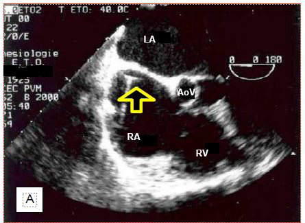
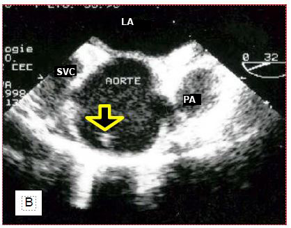
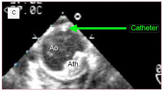
Figure 7.33: Location of central line chuck on TEE. A: Chuck in correct position in the right atrium. B: Chuck incorrectly located in the ascending aorta. C: Catheter positioned in the descending aorta. RPA: right pulmonary artery. SVC: superior vena cava. PA: pulmonary artery trunk. Ao: Aorta. Ath: aortic atheroma.
If the chuck is not visible in the RA when introduced more than 20 cm into the central vein, the search should aim at the ascending aorta, where it can be located above the aortic valve. If not, it should still be looked for at the junction between the arch and the descending aorta, as the "J" at its tip may direct distally into the aorta, depending on the angle at which it abuts the wall. To be able to visualise the cannula or catheter correctly, the metal chuck, which is very echogenic, must be removed. In addition to checking their own catheters, the anaesthetist can guide the placement of particular cannulas that need to be precisely positioned. For example, venous cannulae placed in the RA and superior vena cava (SVC) from a femoral insertion will easily abut the fossa ovale membrane, or pass into the LA through a patent foramen ovale (PFO); ultrasound can guide the operator in manoeuvring to target the SVC (Figure 7.34).
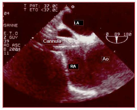
Figure 7.34: Venous cannula ascended from the femoral vein into the RA where the TEE discovers that it abuts the angle between the interatrial septum and the root of the aorta instead of threading into the superior vena cava.
It is possible to visualise the cannula in the coronary sinus during retrograde cardioplegia [10]. Some flexible arterial cannulae are inserted on a guidewire into the ascending aorta or right subclavian; the position of the distal end of the cannula in the arch can be monitored with TEE. When placing a ventricular assist, the position of the arterial and venous cannulae can be monitored and the flow measured (Figure 7.35) [17].
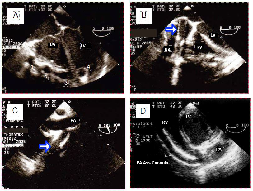
Figure 7.35: Biventricular assist cannulae (Thoratek™). A: the 4 cannulae on the anterior aspect of the heart; 1: cannula coming from the RA; 2: cannula going into the aorta; 3: cannula going into the PA; 4: apical cannula in the LV. B: cannula in the RA; this cannula is too deep and presses hard against the interatrial septum. C: cannula anastomosing to the pulmonary artery (PA). D: In transgastric view, the RV assist cannula is followed into the right outflow tract.
In general, a catheter in a vessel is more easily identified when a cross-sectional plane perpendicular to the vessel axis is used. Because TEE is a two-dimensional imaging technique which is a tomography; a catheter may be parallel to the longitudinal plane (long axis of the vessel), and thus escape the observer if the ultrasound field of view passes forwards or backwards but never intersects it. To check the exact positioning of an object, two perpendicular cross sections must be used.
Atheromatosis of the aorta
Examination of the descending aorta can be used to decide whether atheromatosis is such that it contraindicates placement of an intra-aortic counterpulse (IABP) prior to weaning off pump (Figure 7.36) (Video).
Video : Short axis view including mobile atheroma
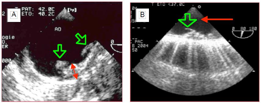 Figure 7.36: Two TEE images of atheromatosis of the descending aorta. A: Atheromatous masses protrude into the lumen and the endovascular surface is completely irregular; the double red arrow indicates the thickness (about 1 cm). B: A pedunculated atheroma floats in the lumen like a bell; this situation is highly emboligenic. The red arrow indicates the direction of flow.
If necessary, TEE offers the possibility of positioning the IACP correctly (height) without interruption required by radiological control: the tip of the catheter should be 1 cm below the start of the left subclavian. If the guidewire is not visible in the descending aorta, one must beware of a serious problem on the way from the femoral artery: dissection, winding in an abdominal aneurysm, wrong direction.
As the oesophagus and descending aorta run side by side in the chest, TEE is a preferred examination of this part of the aorta. However, the interposition of the right bronchial stump between the oesophagus and the ascending aorta limits visibility to the first 5-6 centimetres of the ascending aorta (Figure 7.37) and the distal part of the arch [19].
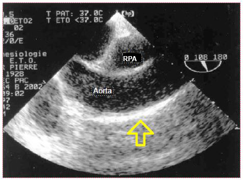
Figure 7.37: Atheromatosis of the ascending aorta; presence of a long plate of atheromatosis on the anterior aspect of the aorta in longitudinal view, in the area used for ECC cannulation.
As surgical palpation is unreliable, epi-aortic ultrasound is the only way to investigate the entire ascending aorta, to select the site of cannulation, and to reduce the incidence of cerebral embolism (see Chapter 27 Epi-aortic ultrasound and Figure 27.70) [14,16]. TEE can be used to determine the indication for an epi-aortic examination based on the degree of involvement of the descending aorta, as there is a good correlation between atheromatous lesions in the two segments of the thoracic aorta [9]. In case of extensive and thickened (stage III), protruding (stage IV) or friable (stage V, pendulous lesions, "porcelain" aorta) lesions in the ascending aorta, a change of surgical strategy for arterial bypass grafting is recommended [11].
- Cannulation through the right subclavian artery.
- Cannulation through a femoral artery; this option has two major risks:
- Cerebral embolisation by atheromatous material from the descending aorta as the flow is retrograde;
- Acute dissection by flow infiltration through the plates.
- Use of an aortic cannula with expandable filter (Embol-X™).
- Occlusion with an intravascular balloon mounted from the femoral (Heartport™).
- No cardioplegia cannulation or aortic clamping: operation with beating heart or ventricular fibrillation if possible.
- For coronary artery bypass grafting: multiple arterial grafts from the mammary arteries or the descending aorta.
- In extreme cases, replacement of the ascending aorta with a prosthesis.
Intra-aortic balloon
To avoid clamping an overly fragile aorta, an inflated balloon is sometimes used in the ascending aorta as a clamp. This technique involves echocardiographic monitoring of particular phenomena, like displacement of the balloon which moves either distally towards the aortic valve or proximally towards the vessels of the arch [21].
- Position of the balloon at the sino-tubular junction;
- Possible protrusion of the balloon between the aortic valves;
- Possible distal displacement of the balloon (disappearance of the TEE view of the root of the aorta);
- Presence of aortic insufficiency;
- Cardioplegia flow in the proximal part of the aorta.
Iatrogenic dissection of the aorta
Aortic wall dissection by the arterial cannula is a dramatic iatrogenic complication that occurs early in the CABG procedure; the same can happen with the cardioplegia cannula or during peripheral femoral or subclavian cannulation. The event is characterised by sudden hypotension and overpressure in the arterial line. The diagnosis can be made immediately by TEE [12]. In case of A or B aortic dissection, colour Doppler flow analysis provides certainty that the cannula is perfusing the true lumen. Similarly, when stents are inserted, the echocardiographic image can be used to check that the guidewire will deliver the stent into the true lumen and not into the false lumen of the dissection or aneurysm.
A misleading image may occur early in bypass surgery when femoral arterial cannulation is performed, suggesting retrograde dissection of the descending aorta [22]. ECC perfusate, which is colder and more fluid than blood, does not mix immediately with blood; two parallel layers are momentarily formed in the aorta which may appear to be separated into a true and a false lumen. This effect resolves in 30-40 seconds. Arterial cannulation of ECC in the femoral position may cause retrograde dissection of the abdominal and descending aorta, which appears on TEE as a membrane (flap) floating in the aortic lumen.
Diagnosis of anatomical malformations
Some benign congenital malformations go unnoticed during life, but can cause problems in the special situation of cardiac surgery. Examples are patent foramen ovale (PFO), atrial septal defect (ASD), or left superior vena cava (LSVC). The presence of a transatrial communication is not dangerous as long as the pressure in the OG remains higher than in the RA and the atria are sealed. If the POD increases (PEEP, pulmonary hypertension, right-sided failure), the shunt reverses and creates hypoxaemia by right-to-left shunting. When one of the two atria is opened to room air by the operator, bubbles can enter the other. In left heart surgery (e.g. mitral valve surgery), the PFO or AIC is a source of continuous bleeding from the RA that floods the surgical field. Surgery on the right heart (e.g. tricuspidoplasty, resection of the right flush chamber) is possible with a beating heart procedure provided that the interatrial septum is sealed, otherwise air can enter the LA and embolise into the arterial circuit (paradoxical embolism). It is therefore important to explore the interatrial septum with TEE and if necessary perform a microbubble test (Figure 7.38) (Microbubble video). The same applies when proceeding a left ventricular assist.
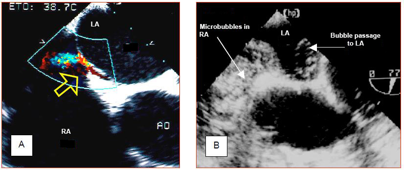
Figure 7.38: Patent foramen ovale (PFO). A: Left-right flow through the PFO as seen on the colour Dopper. B: Microbubble test. Central injection of 10 ml 0.9% NaCl previously agitated to create microbubbles by cavitation fills the entire RA and demonstrates the passage of bubbles into the LA. The first image demonstrates the L-R passage, while the second illustrates the R-L passage, if it exists at all. Either image is sufficient to make the diagnosis of PFO.
Video : micro bubbles test : right to left passage when RA pressure excedes LA pressure in a cardiac cycle.
A PFO is a common finding in the normal population; its incidence varies from 5-10% on two-dimensional echocardiography, to 24% at autopsy or 27% on direct intraoperative inspection, where it presents as a cleft of about 20 mm [1,5,18]. The finding of an unknown ASD is rarer.
The left superior vena cava (LSVC) in the vast majority of cases drains into the coronary sinus; the latter is dilated due to increased flow. In the absence of right ventricular failure and major tricuspid insufficiency, the finding of coronary sinus dilatation should raise suspicion of the diagnosis (Figure 7.39) (Video). The right superior vena cava may be present or absent, which obviously poses a problem for the central line.
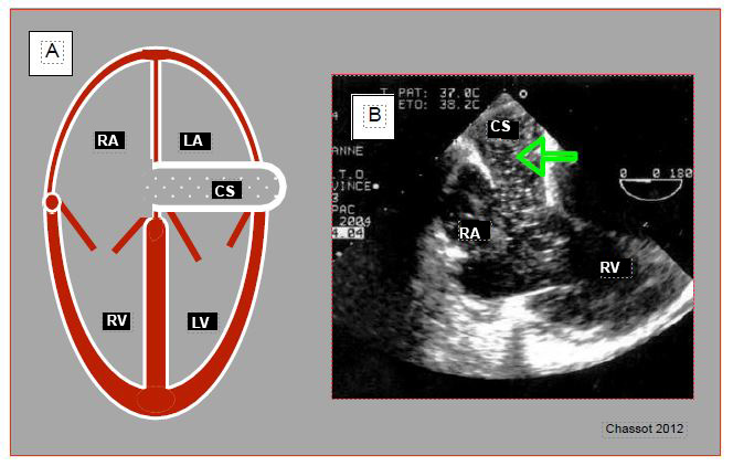
Figure 7.39: Left superior vena cava (LSVC). A: schematic representation of coronary sinus (CS) dilation (≥ 1.5 cm) in 4-cavity view. B: injection of microbubbles into a left upper limb vein; they appear in the coronary sinus (arrow) before arriving in the RA.
Video : major coronary sinus dilation in a case presenting a left superior vena cava; coronary sinus appears like a vertical tube upscreen draining in RA; hypertrophic RV tetralogy of Fallot.
The presence of an LSVC raises two issues for the surgeon.
- Retrograde cardioplegia is impossible because the perfusate leaks into the systemic circulation without perfusing the heart;
- The LSVC flow continuously feeds the RA during separate cava cannulations and energises the RA.
LSVC also raises two problems for the anaesthetist: the risk of coronary sinus thrombosis contraindicates the use of a long-term CVP, and Swan-Ganz insertion is not possible via the left jugular or subclavian track.
Aortic insufficiency
Even without clinical translation, aortic insufficiency (AI) is potentially dangerous in the context of bypass surgery. As soon as the heart rate slows down during cooling, the aortic valve leaks into the LV under the pressure generated by the pump and dilates it. On the other hand, cardioplegia delivered through the aortic root after aortic clamping flows largely into the ventricle through the aortic leak; the LV is strained and expands as it no longer contracts and cannot eject what it receives. The rate of incidental finding of IA by TEE before bypass surgery is 5% (Figure 7.40) (IA video) [5].
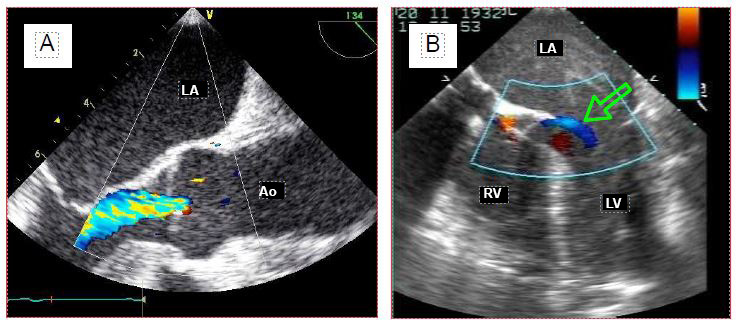
Figure 7.40: Aortic insufficiency (AI). A: Long-axis view of the aortic root; the colour jet in the LV outflow tract indicates the presence of AI. B: During cardioplegia, the aortic valve is continuously leaking into the LV, as evidenced by the blue flow (arrow) into the left outlet chamber (4-cavity view).
Video : moderate aortic insufficiency, long axis view 130° from aortic root.
It is essential to monitor the LV at the start of ECC and during cardioplegia to alert the operator to any dilatation, who may interrupt the perfusion, compress the ventricle by hand, or drain it (Video). The same attention is paid to the LV when performing surgery in continuous ventricular fibrillation or when implanting a left ventricular assist.
Video : Intraventricular cardioplegia leak in AI; even minor the flow leads to a potential dilation of the ventricle
Intracavitary thrombus
Thrombus is suspected in the left atrial appendage in cases of atrial stasis or fibrillation (mitral stenosis, left ventricular failure) when spontaneous contrast is seen in the RA on routine examination (Figure 7.41) (Video).
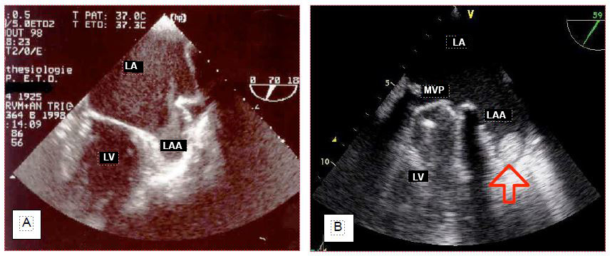
Figure 7.41: Stasis and thrombus in the left atrial appendage (LAA). A: Spontaneous contrast in the LAA. B: Small thrombus found incidentally in the LAA in a patient with a dysfunctional mitral valve prosthesis (mechanical valve, MVR).
Video : left atrial appendage thrombus; prosthetic valve in mitral position
In cases of apical akinesia and left ventricular dysfunction (EF < 0.35), a thrombus can be found at the LV apex (Figure 7.42) (Video).
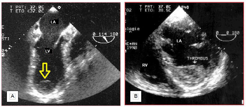
Figure 7.42: Parietal thrombus in the LV. A: apical thombus in a case of apical akinesis 10 days after infarction; this thrombus is weakly implanted and can easily embolise. B: Laminar wall thrombus overlying an anteroseptal akinetic zone. This type of thrombus is firmly anchored in the trabeculations; it is best left in place, as its removal will fragment it and increase the risk of embolism.
Video : thrombus extended to the LV apex.
This information is crucial for the surgeon, who must avoid dislodging these thrombi by manipulating the heart, given the risk of embolisation. The decision to explore the cavity concerned to remove thrombus depends on its mobility and is the result of a consilium between the anaesthetist, the surgeon and possibly the cardiologist. A thrombus may also be discovered in a left cavity at the end of the operation, when intraoperative anticoagulation was insufficient. In this case, the mobility and the embolic risk require an immediate return on bypass to remove the thrombus (Figure 7.43) (Video).
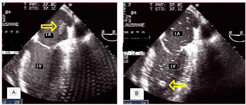
Figure 7.43: Thrombus in the LA at the end of bypass surgery (incidental finding). A: Thrombus floats to the left superior pulmonary vein junction. B: thrombus floats into the LV. Immediate return to bypass surgery is imperative to retrieve it before it embolises in the periphery. Its size makes it a good candidate to obstruct a carotid artery. Many bubbles float in the LA and the LV.
Inadvertent invagination of the left atrial appendage during surgery may resemble a thrombus in the LA.
Debulking at the end of ECC
Air enters the left chambers during cardiotomy and accumulates in the areas at the zenith of the cardiac chambers in the supine position: the right superior pulmonary vein, the top of the interatrial septum in the LA, the mitro-aortic angle, the anteroapical septum in the LV, and the right sinus of Valsalva. Gas emboli occur in 75% of patients operated on for left heart valve disease [20]. Air can also enter coronary artery bypass grafts and the right coronary artery, because they are implanted on the anterior aspect of the aorta. Air bubbles appear on TEE as bright white particles that follow the blood flow or accumulate in the reperfused tissue (Figure 7.44).
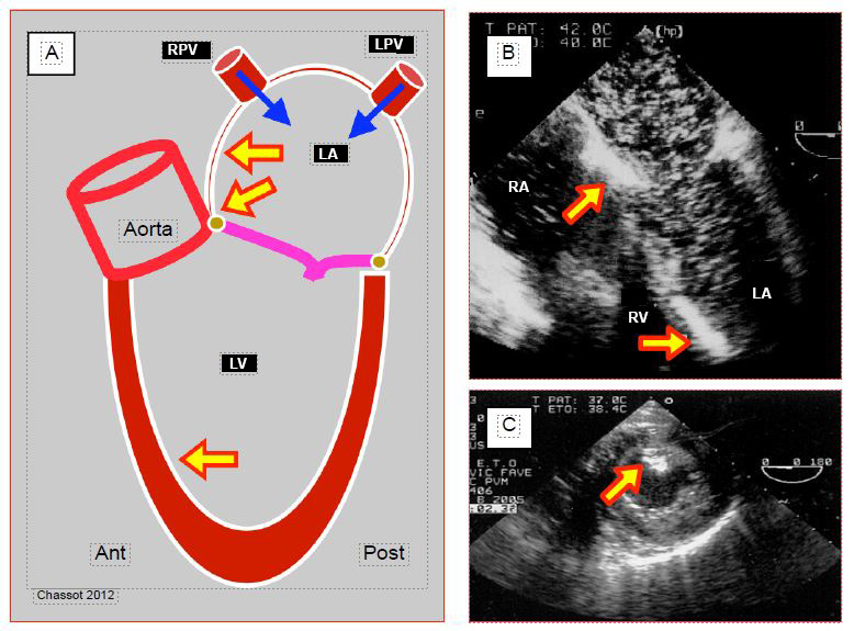
Figure 7.44: Air accumulation in the left heart at the end of bypass. A: Air originates from the left cardiotomy and the right (VPD) and left (VPG) pulmonary veins; it tends to accumulate at the most elevated sites: angle between the interatrial septum and the roof of the LA, mitro-aortic angle, antero-apical interventricular septum (in Trendelenburg position). B: 4-cavity view with innumerable bubbles in the LA and LV, as well as two areas of accumulation against the interatrial septum and in the trabeculations of the anteroapical interventricular septum. C: Air embolisation in the posterior papillary muscle (right coronary territory).
Air bubbles are highly echogenic and take two different shapes [5].
- Miliary microbubbles, tiny and low contrast; they have no impact on the postoperative neurological status.
- Small, bright shuttles that dance in the heart chambers (Video) and accumulate in large sheets in overhanging areas. Their identification and localisation on TEE allows for more adequate emptying, and thus may improve the neurological prognosis of patients.
Video : accumulation of microbubbles in left atrium and ventricle before weaning off pump
Flooding the pericardial cavity with a constant flow of CO2 (1-2 L/min) during the operation replaces the air with a gas that is more soluble in the blood and thus reduces the size and number of bubbles.
Weaning off pump
Finally, TEE is an essential tool for solving problems that arise when weaning off pump : hypovolaemia, LV or RV dysfunction, acute ischaemia in a coronary territory, prosthetic valve dysfunction, problems with surgical correction, cardiac output assessment, etc.
| TEE during ECC |
| Transoesophageal echocardiography (TEE) has several points of impact in relation to ECC:
- Identification of risks (aortic atheroma, aortic insufficiency, intracardiac thrombus)
- Identification of iatrogenic lesions (aortic dissection, VSD)
- Anatomical anomaly (PFO, ASD, left superior vena cava)
- Cannula positioning (vena cava cannula, coronary sinus catheter, IABP)
- Air removal
- Assessment of blood volume and ventricular function before weaning
- Assessment of segmental contractility (anastomosis redo)
|
© CHASSOT PG, GRONCHI F, April 2008, last update, December 2019
References
- AGOUSTIDES JGT, Weiss SJ, Weiner J, et al: Diagnosis of patent foramen ovale with multiplane transesophageal echocardiography in adult cardiac surgical patients. J Cardiothorac Vasc Anesth 2004; 18:725-30
- BETTEX DA, CHASSOT PG. Transoesophageal echocardiography in intensive care anaesthesia. Paris, Pradel-Masson, 1997
- BETTEX DA, SCHMIDLIN D, BERNATH MA, PRETRE R, HURNI M, CHASSOT PG. Intraoperative transesophageal echocardiography in pediatric congenital cardiac surgery: A two-center observational study. Anesth Analg 2003; 97:1275-82
- BRANDT RR, OH JK, ABEL MD, et al. Role of emergency intraoperative transesophageal echocardiography. J Am Soc Echocardiogr 1998; 11:972-7
- CHASSOT PG. Retrospective and prospective analysis of 12'986 intraoperative transesophageal echocardiograms. CHUV, 2008. Unpublished data
- ELTZSCHIG HK, Rosenberger p, löffler m, et al. Impact of intraoperative transesophageal echocardiography on surgical decisions in 12,566 patients undergoing cardiac surgery. Ann Thorac Surg 2008;85:845-53
- HAHN RT, ABRAHAM T, ADAMS MS; et al Guidelines for performing a comprehensive transesophageal echocardiography examination: Recommendations from the American Society of Echocardiography and the Society of Cardiovascular anesthesiologists. J Am Soc Echocardiogr 2013; 26:921-64
- KALLMEYER IJ, COLLARD CD, FOX JA, et al. The safety of intraoperative transesophageal echocardiography. Anesth Analg 2001; 92:1126-30
- KONSTADT SN, REICH DL, KAHN R, et al. Transesophageal echocardiography can be used to screen for ascending aortic atherosclerosis. Anesth Analg 1995; 81:225-33
- LICINA MG, SAVAGE RM, HEARN CH, KRAENZLER EJ. The role of transesophageal echocardiographhy in perfusion management. Semin Cardiothorac Vasc Anesth 2001; 5:321-34
- MENKIS AH. Management of the ascending aorrta in routine cardiac surgery. Semin Cardiothorac Vasc Anesth 2004; 8:19-24
- MICHAELS IK, NEUSTEIN SM. Sudden hypotension before cardiopulmonary bypass. J Cardiothorac Vasc Anesth 1998; 12:231
- MICHEL-CHERQUI M, CEDDAHA A, LIU N, et al. Assessment of systematic use of intraoperative trasesophageal echocardiography during cardiac surgery in adults: A prospective study of 203 patients. J Cardiothorac Vasc Anesth 2000; 14:45-50
- MURKIN JM, MENKIS AH, DOWNEY D, et al. Epiaortic scanning decreases cerebral emboli during aortic cannulation and application of partial occlusion clamp. Ann Thorac Surg 1999; 68:1461-7
- REEVES ST, FINLEY AC, SKIBAS NJ, et al. Basic perioperative transesophageal echocardiography examination: a consensus statement of the American Society of Echocardiography and the Society of Cardiovascular Anesthesiologists. Anesth Analg 20113; 117:543-58
- REEVES ST, GLAS KE, ELTZSCHIG H, et al. Guidelines for performing a comprehensive epicardial echocardiographic examination: Recommendations of the American Society of Echocardiography and the Society of Cardiovascular Anesthesiologists. J Am Soc Echocardiogr 2007; 20:427-37
- SCALIA GM, McCARTHY PM, SAVAGE RM, et al. Clinical utility of echocardiography in the management of implantable ventricular assist devices. J Am Soc Echocardiogr 2000; 13:754-63
- SCHNEIDER B, ZIENKIEWICZ T, JANSEN V, et al. Diagnosis of patent foramen ovale by transesophageal echocardiography and correlation with autopsy findings. Am J Cardiol 1996; 77:1202-9
- SYLVIRIS S, CALAFIORE P, MATALANIS G, et al. The intraoperative assessment of ascending aortic atheroma: epiaortic imaging is superior to both transesophageal echocardiography and direct palpation. J Cardiothorac Vasc Anesth 1997; 11:704-10
- TINGLEFF J, JOYCE FS, PETTERSON G. Intraoperative echocardiography study of air embolism during cardiac operations. Ann Thorac Surg 1995; 60:673-7
- VISTARINI N, AIELLO M; MATTIUCCI G, et al. Port-access minimally invasive surgery for atrial septal defects: a 10-year single-center experience in 166 patients. J Thorac Cardiovasc Surg 2010; 139:139-45
- WALKE CM, CLEMENTS F, GLOWER DD, et al. False-positive diagnosis of aortic dissection associated with femoral cardiopulmonary bypass. Anesthesiology 1998; 88:1119-21