As with mitral regurgitation, the current surgical trend is to perform aortic valve repair whenever possible, rather than replacing the valve with a prosthesis from the outset. This avoids the risks of anticoagulation associated with mechanical valves and the problem of degeneration associated with bioprostheses. However, aortic valve repair is more delicate than mitral valve repair and is not as widely performed. Intraoperative TEE therefore plays a crucial role in deciding whether reconstruction is feasible and in assessing the quality of the repair after ECC. Pre-ECC evaluation modifies the surgical plan in 11-25% of patients and justifies reoperation in 4-6% of cases [13].
A brief review of the anatomy is useful before discussing the echocardiographic images (Figure 11.131).
- The 3 cusps of the aortic valve are suspended at the sino-aortic junction by the 3 commissures; their lower insertion is on the virtual basal ring, which is anatomically located in the LV outflow tract (LVOT), below the junction between the aorta and the LV. Its length is slightly less than the distance between the aortic annulus and the coronary ostia.
- Their U-shaped insertion defines 3 interval fibrous triangles in the wall of the sinuses of Valsalva, which form a support ring for the cusps (Figure 11.132).
- The aortic "ring" is simply the narrowest point of the LVOT - aortic root - ascending aorta assembly; by convention, it is also the point at which the diameter of the base of the aortic valve is measured. Its shape is not circular, but elliptical like that of the outflow tract; the ratio between the small and large diameter of this ellipse is approximately 0.7 (mean 26.3 mm and 23.5 mm) [17,24]. What we define as the aortic functional ring is therefore a virtual structure located in the LVOT, with an oval cross-section, corresponding to the most anterior insertion point of the 3 aortic cusps in systole. The 120-140° long axis TEE plane, in which the diameter of the aortic annulus is measured, cuts the oval of this annulus at its smallest diameter (Figures 11.133 and 11.134). Two-dimensional TEE therefore underestimates the true diameter of the aortic annulus for two reasons [16,17]:
- The mid-esophageal long-axis view (120-140°) cuts the elliptical ring at its small diameter (sagittal plane);
- The section plane does not pass through the centre of the ring but slightly in front of it.
- The sinuses of Valsalva are bulges in the ascending aorta at the level of each cusp; their presence prevents the cusps from sticking to the wall in systole and from closing quickly enough in diastole.
- The sino-tubular junction is where the ascending aorta begins, in the form of a regular tube with a circular cross-section.
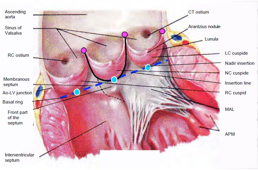
Figure 11.131: Open aortic valve in situ. The 3 cusps are inserted in a "U" shape into the aortic root (black line); they are suspended at the level of the sino-aortic junction and are articulated by a hinge at the nadir of their insertion (blue dots); these 3 points are located on the basal ring (blue line), which is anatomically located in the LV outflow tract, below the junction between the aorta and the LV. This is the narrowest part of the LVOT-aortic root assembly; it is also the structure measured on echo as the aortic annulus, but this "structure" has no anatomical correlate. The 3 commissural points (purple dots) are located at the sinotubular junction. AV: Atrioventricular. RC: right coronary. LC left coronary. AML: anterior leaflet of the mitral valve. PM: papillary muscle. NC: non-coronary. CT: common trunk.
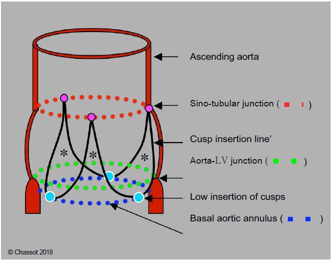
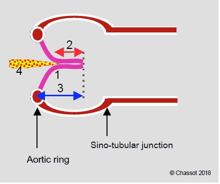
Figure 11.132: Schematic diagram of the aortic root. The 3 cusps are inserted in a "U" shape into the aortic root (black line) at the level of the sinuses of Valsalva; they are suspended at the level of the sinotubular junction (red dotted line) and are articulated by a hinge at the nadir of their insertion (blue dots); these 3 points are located on the basal ring (blue dotted line), which is actually in the LV outflow tract, below the junction between the aorta and the LV (green dotted line). This basal ring, which is anatomically virtual, is the narrowest point in the LVOT - aortic root - ascending aorta system; by convention it is the point at which the diameter of the aortic "ring" is measured. Its shape is elliptical rather than circular. The 3 commissural points (purple dots) are located at the sino-tubular junction; they are 5-10% dilated with respect to the points of the basal ring. *Fibrous triangles in the wall of the sinuses of Valsalva supporting the cusps.
The plane intersecting the largest diameter of the annulus is a long axis plane, known as the coronal or left-right plane, which is perpendicular to the long axis plane at 120° and intersects it according to the blue line in Figure 11.133. This frontal plane cannot be used in TEE because it is anterior to the oesophagus and does not pass through the probe sensor. It can only be visualised using three-dimensional reconstruction (3D TEE). The 0° deep transgastric view provides a close view of this third plane, but is not exactly co-planar with it, and provides distant and imprecise images of the aortic valve. It is therefore not a substitute for 3D reconstruction. The distance between the annulus and the right coronary ostium is clearly visible in the long-axis 120-140° 2D plane (Figure 11.134), but the distance between the annulus and the left ostium (common trunk) is not accessible on 2D TEE, as it lies precisely in the left-right coronal plane, which can only be obtained on 3D echo. The average distance between the aortic annulus and each ostium is 13.5 mm [14].
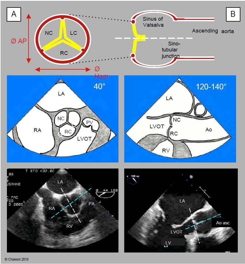
Figure 11.133: Anatomo-echocardiographic correlation of the 2 cross-sectional planes of the aortic valve: retrocardiac mid-esophageal ETO views in short-axis at 40° (A) and long-axis at 120-140° (sagittal section) (B). For each of the two views, the aortic diagram, the TEE view diagram and the two-dimensional TEE image are shown vertically. The aortic annulus is elliptical while the ascending aorta is circular. The anteroposterior diameter (Ø AP) is shorter than the left-right or coronal diameter (Ø Cor). In the short-axis image (left), the white line represents the intersection with the 120-140° plane; in the long-axis image (right), it represents the intersection with the 40° plane. The blue line is the intersection with the third plane, which is a long-axis plane perpendicular to the TEE plane but in front of the oesophageal sensor (left-right, coronal or frontal plane) and does not intersect it; it is therefore only visible in three-dimensional TEE.
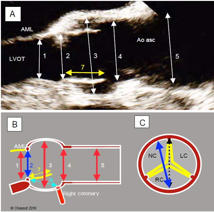
Figure 11.134: Preoperative TEE assessment of aortic diameters. A: 120° long axis diameter. 1: LV outflow tract; 2: aortic annulus (measured on the medial edge, posterior edge to anterior edge); 3: sinus of Valsalva; 4: sino-tubular junction; 5: ascending aorta (at the crossing of the right pulmonary artery); 7: height of cusp. Diameters are measured in systole. AML: anterior leaflet of the mitral valve; LVOT: LV outflow tract. B: Schematic representation of the same diameters. 6: distance between the aortic annulus and the right coronary ostium; 7: height of the right cusp (yellow); normally 6 > 7. C: diameter of the aortic annulus (in blue) measured in the 120° long-axis view projected onto the short-axis view; it is slightly narrower than the actual anatomical diameter (dotted line) because it does not actually pass through the centre of the annulus, but slightly anterior to it.
Two-dimensional echocardiography
Mild asymptomatic aortic insufficiency (AI) occurs in 1% of the young population, 5% of adults and up to 13% of the elderly [7]. Although it has no clinical significance, it may cause acute dilatation of the LV when it slows and then stops beating at the time of cardioplegia and aortic clamping at the start of ECC. It should therefore be systematically investigated prior to any bypass surgery.
Video: Intraventricular leak from cardioplegia in even minor aortic insufficiency, when the LV stops and no longer ejects; this flow leads to dangerous dilation of the ventricle.
By analogy with the classification of MIs, 3 types of AI are described, with the first type being subdivided into 4 categories (see Figure 11.127) [2,4.19].
- Type I: Normal cusps, dilatation of the aortic root; central AI jet.
- Ia: Dilatation of the sinotubular junction and ascending aorta;
- Ib: Dilatation of the sinuses of Valsalva (aortic root);
- Ic: dilatation of the aortic annulus;
- Id: Perforation of a cusp.
- Type II: Excess tissue and movement of one or more cusps, prolapse; eccentric jet.
- Type III: restrictive movement of the cusps, fibrosis, commissural fusion, calcifications; variable jet.
The examination of the valve is accompanied by the examination of the aortic root and its dimensions (120° long-axis view and 3D reconstruction), which allows the description of three different phenotypes in type I (measurements taken in telediastole, except for the aortic annulus, which is measured in mesosystole) [1,19].
- Dilatation of the aortic annulus; normal diameter: 2.1-2.3 cm in women, 2.3-2.6 cm in men;
- Aortic root aneurysm: diameter at the level of the sinuses of Valsalva > 4.5 cm;
- Aneurysm of the ascending aorta: diameter > 5.0 cm.
Volume overload in the diastolic pressure regime of the aorta leads to a very pronounced dilatation of the LV (telesystolic diameter > 5.0 cm, end-diastolic diameter > 7.0 cm, Vts > 50 mL/m2, Vtd > 135 mL/m2). The 2D image of the AI is characteristic (Figure 11.135).
- Dilatative hypertrophy and spherification of the LV, moderate dilatation of the LA.
Video: Dilatative hypertrophy of the LV in a case of aortic insufficiency.
- Dilatation of the aortic root.
Video: dilatation of the aortic root leading to diastolic non-coaptation of the cusps in Marfan syndrome (simultaneous long-axis and short-axis views).
- Prolapse or tear of a cusp protruding into the LVOT in diastole, retraction of one or more cusps (120° long axis view).
Video: Prolapse of the anterior cusp in aortic bicuspidism in 120° long-axis view.
Video: Colour flow illustrating diastolic regurgitation in the same case as in the previous video.
- Central coaptation defect with triangular regurgitant orifice in diastole (40° short-axis view from mid-esophagus).
- Diastolic bulging of the body of the anterior leaflet of the mitral valve into the LA; jet lesion at the point of impact of the AI on this anterior leaflet.
- Diastolic vibration of the anterior leaflet of the mitral valve caused by the high-speed jet of the AI (origin of the flint roll).
Video: Flint roll; if it is directed towards the tip of the anterior mitral leaflet, aortic insufficiency causes it to vibrate in diastole.
Figure 11.135: Two-dimensional images of AI. A: Normal level of coaptation of the aortic cusps. B: Prolapse of the right coronary cusp. C: Non-coronary cusp prolapse in transgastric view. D: Central regurgitant orifice during dilatation of the annulus; the area of the orifice (0.6 cm2) indicates severe AI.
Doppler echocardiography
The most characteristic image of AI is the presence of a swirling diastolic jet in the LVOT, the extension of which towards the LV is a rapid qualitative method of assessing the extent of regurgitation [18].
Video: Moderate aortic insufficiency in 130° long-axis view of the aortic root.
Video: 50° short-axis view of the triangular central regurgitation orifice, highlighted by the persistent colour flow in diastole.
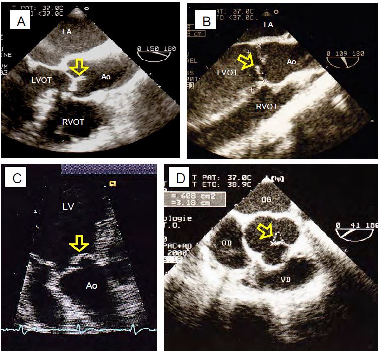
However, the performance of this method is poor as it is dependent on haemodynamics, device settings and the angle of analysis. The size of the jet depends on its Vmax, which is a function of the ΔP between the aorta and LV in diastole; it increases or decreases in parallel with aortic diastolic pressure; it also varies with aortic and LV compliance [3]. Assessment of the diastolic colour jet should include the upstream part (PISA), the passage through the valve (vena contracta) and the jet in the LVOT and LV. The morphology of the jet is an important source of information (Figure 11.136 and Figure 11.137) [9].
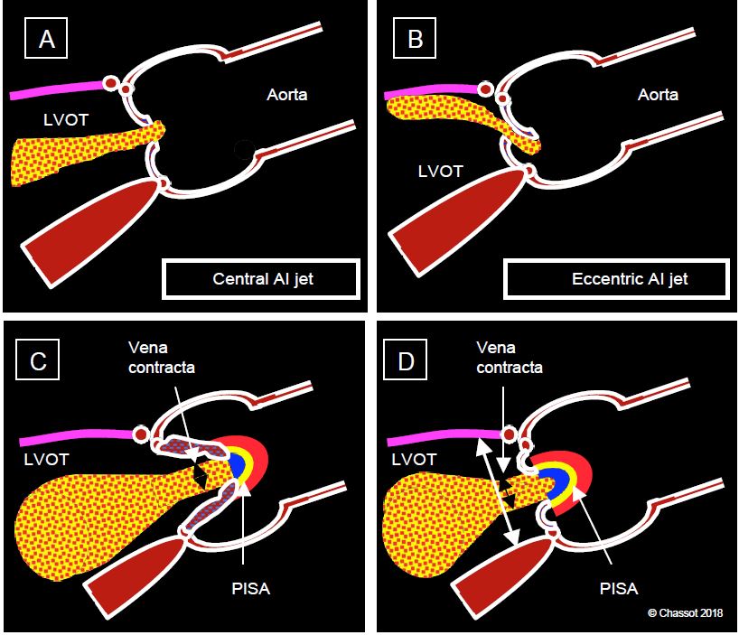
Figure 11.136: Aortic regurgitation. A: Central AI jet in case of dilatation of the annulus (aortic root disease). B: Eccentric jet in case of lesion of an aortic cusp (prolapse). C: Measurement of the diameter of the vena contracta just after the valve. D: Ratio of the diameter of the jet to that of the outflow tract at the same level.
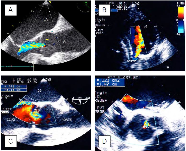
Figure 11.137: Colour Doppler flow in an AI. A: Central AI in long axis view of the ascending aorta. B: Central AI in deep transgastric view. C: Eccentric AI in long-axis view of the middle oesophagus. D: AI in short axis view.
- A circularly symmetric central jet indicates leakage due to dilatation of the ring without damage to the cusps.
Video: Central aortic insufficiency due to dilatation of the aortic root in Marfan syndrome (160° long-axis view).
- An eccentric jet is due to damage to the valve itself; the leak is directed away from the prolapsing cusp or towards the retracted cusp.
Video: Eccentric aortic insufficiency due to prolapse of the right coronary cusp (130° long-axis view).
- Colour flow consists of 3 zones: the hemispheric convergence (PISA) on the aortic side, the vena contracta at the outlet of the valve into the LVOT, and the swirling zone that widens into the outflow tract and LV.
Video: Severe aortic insufficiency in 120° long-axis view; presence of a zone of concentric acceleration upstream; the width of the jet downstream of the valve is more than half that of the outflow tract.
- The diameter of the vena contracta immediately after the valve reflects the size of the regurgitant orifice and is independent of haemodynamics; a diameter > 6 mm corresponds to severe AI.
- The ratio of the diameter of the vena contracta to that of the LVOT at the same site is ≥ 0.6 in severe AI. It is most accurately measured in the TM mode over the LVOT (see Figure 26.45).
- PISA: In moderate AI the PISA is weak, flattened and unusable for quantification. In severe AI, however, there is a clearly visible zone of concentric acceleration on the aortic side in diastole, which allows the area of the regurgitant orifice to be calculated as in MI. However, the valve often looks like a funnel, so the result must be corrected for the angle formed by the non-planar surface of the valve (α /180), otherwise the regurgitant area will be overestimated: S = (2 π r2 • Valias) / VIA • α/180.
- 3D planimetry avoids the approximation imposed by 2D, which assumes that the orifice is circular, whereas in AI it is typically triangular, elliptical or slotted.
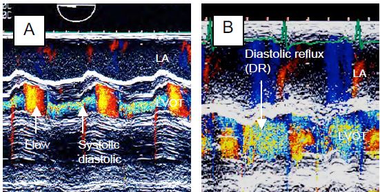
Figure 26.45: TM mode images of aortic insufficiency which appears as a holodiastolic vortex flow. The ratio of the diameter of the AI to that of the outflow tract can be accurately measured with this technique. A: moderate AI; the jet occupies less than one third of the LVOT. B: Severe AI; the jet occupies almost the entire LVOT.
Measurements are more reliable in central AI than in eccentric AI. The latter are associated with deformation of the valve and may originate from a slit-like orifice located at the commissure between two cusps.
Video: Central aortic insufficiency extending to the commissure between the non-coronary cusp and the left coronary cusp (40° short-axis view).
Their size must be observed in several planes. In aortic disease, the axis of the AI is often not the same as the axis of the anterograde flow. The AI jet always appears larger in the transgastric view (0° or 120°) because it is in the axis of the Doppler beam, whereas it is perpendicular to it in the mid-oesophageal views. Flow measurements are usually performed in protodiastole when the transvalvular gradient is maximal [21].
The AI flow recorded by continuous Doppler in the transgastric view gives a spectral trace directed towards the sensor with a characteristic silhouette (Figure 11.138) [5,6,9].
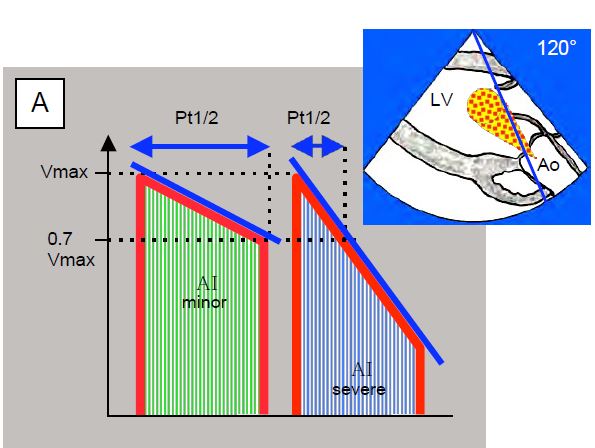
Figure 11.138: Time to half pressure (Pt1/2) in aortic insufficiency; this is the time taken for the pressure to fall by half or for Vmax to fall by a factor of 0.7. The flow of the AI is recorded in a transgastric view at 0° (deep transgastric view) or 120° (long axis transgastric view). A: Diagram of a mild AI (flat deceleration slope) and a severe AI (steep deceleration slope). B: Mild AI; Pt1/2 850 msec. C: Severe AI; Pt1/2 238 msec.
- Maximum speed: 3-4 m/s; the density of the curve depends on the size of the AI.
- Progressive deceleration during diastole; the slope of this deceleration is a direct function of the rate of pressure equalisation between the aorta and the LV. If the regurgitant orifice is small (small AI), the ΔP between the aorta and the ventricle decreases little during diastole and the slope is small. If the orifice is large (severe AI), the ΔP decreases rapidly as the LV fills and the slope is very steep.
- The Vmax at which flow stops at the end of diastole corresponds to to ΔP between aortic pressure and intraventricular pressure (ΔP = 4 V2IA ); subtracting this ΔP from diastolic BP gives LV Ptd.
- The slope of the AI deceleration is used to calculate the half-pressure time (Pt1/2), which is the time required for pressure to fall by 50% or Vmax to fall by 0.7 [6]. A Pt1/2 of < 250 msec corresponds to severe AI. LV compliance significantly modifies Pt1/2: it is shortened in severe diastolic failure due to high LV diastolic pressure and therefore overestimates the importance of AI [3].
When the AI leaks into the LV, a diastolic reflux occurs in the aorta. This retrograde flow, which is proportional to the degree of regurgitation, is visible further back in the aorta the greater the leak [20]. In severe AI it is visible in the descending aorta (Figure 11.139). Its presence only in the ascending aorta is not a criterion for severe AI.
The echocardiographic criteria defining severe AI are as follows (see Table 11.13) [9,15,22,25]:
- Dilatative hypertrophy of the LV (telediastolic diameter > 4 cm/m2 ); absent in acute AI;
- Regurgitant jet extending to the midventricle;
- Vena contracta diameter > 0.6 cm;
- Ratio of AI jet diameter to LVOT diameter > 0.6;
- Pt1/2 of diastolic flow < 250 msec;
- Regurgitant volume ≥ 60 ml (regurgitant fraction ≥ 45%);
- Regurgitant orifice area > 0.3 cm2;
- Diastolic regurgitation in the descending aorta.
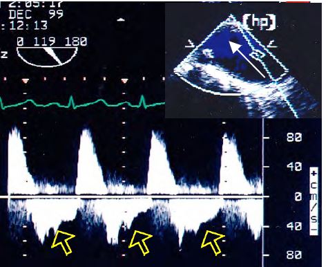
Figure 11.139: Flow in the descending aorta in severe AI with significant holodiastolic reflux (arrows). The flow is recorded with the Doppler axis continuous along the edge of the screen to be as aligned as possible with the flow in the descending aorta as seen in the long axis (90-120°).
3D echo
The most informative image is the 3D en face reconstruction of the aortic valve seen from the aorta, with the right coronary cusp as the most anterior element. By cutting perpendicular to the LVOT-atrial axis, it is possible to measure the diameter and cross-sectional area of the LVOT and aortic annulus, which are elliptical rather than circular, whereas 2D echo can only measure the small diameter [21]. Planimetry of the valve orifice in systole and diastole is achievable in 92% of cases [11].
A multi-step approach is recommended for 3D imaging (Figure 11.140) [14,16].
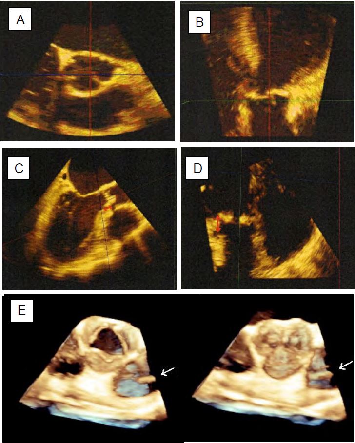
Figure 11.140: Preoperative measurements of the aortic root using 3D TEE. A: Short axis of the aortic annulus (transverse plane). B: Long axis of the annulus (coronal plane); this plane is not possible with 2D TEE. C: Measurement of the distance to the right ostium. D: Measurement of the distance to the left orifice. E: Normal aortic valve seen en-face in systole and diastole; the arrow indicates the presence of a pulmonary catheter in the PA.
- Centre the short-axis and long-axis images of the valve in the centre of the screen; the quality of the 2D image determines the quality of the 3D reconstruction.
- Acquisition in full-volume mode of a volume containing the LVOT, the aortic root and the beginning of the ascending aorta; acquisition is performed in apnea.
- Orientation of the transverse, sagittal and coronal planes on the reconstructed volume.
- Transverse section through the most anterior part of the cusps (points of articulation with the aortic ring); the ring is oval in shape.
- Measurement of ring diameter in sagittal plane (small diameter) and coronal plane (large diameter).
- Measurement of cusp height.
- Measurement of the distances between the aortic annulus and the right ostium (sagittal plane) and between the annulus and the left ostium (coronal plane).
- Diameter of the entire aortic root in 120-140° long axis view or 3D reconstruction.
- Aortic ring: 2.2-2.6 cm;
- Sinus of Valsalva: 3.0-3.4 cm;
- Sinotubular junction: 2.6-2.9 cm;
- Proximal ascending aorta: 2.7-3.0 cm.
- Height of coaptation: 5-8 mm;
- Cusp height: 1.2-1.4 cm;
- Ring-coronary distance: 1.5 cm.
- Type Ia: Telediastolic verification of the size of the aortic annulus and the sinuses of Valsalva, which must not be dilated. The AI jet must be central.
- Type Ib: The sinotubular junction is obliterated and dilated, and the sinuses of Valsalva are dilated. The AI is due to an outward displacement of the commissures; the triangular regurgitant orifice is clearly visible in the 40° short axis; the AI is central.
- Type Ic: Dilatation of the aortic annulus (diameter > 26 mm); the AI jet is central.
- Type Id: The colour jet originates from the body of a cusp (perforation, fenestration); its direction is variable. At a short axis of 40°, the commissure is watertight.
- Type II: a cusp tilts into the LVOT in diastole, producing an eccentric AI jet directed to the opposite side. The jet from a prolapsed right coronal cusp is directed posteriorly, that from a prolapsed left coronal cusp (LC) or non-coronal cusp (NC) is directed anteriorly. It is not possible to differentiate between LC and NC on a 120-140° long axis view, but only on a 40° short axis view or in 3D. The prolapse may be a simple tilting of the distal end of a cusp, or it may be completely everted in the LVOT (flail leaflet); in the latter case, the short-axis section of the LVOT shows a circular structure, which is the section of the prolapsing cup.
- Type III: The leaflets are fibrosed, retracted, partially calcified and the commissures are fused in the 40° short axis. In systole there is usually a curved deformity as in bicuspidism (see Figure 11.150C). The AI jet is more or less central depending on the degree of symmetry of the lesions.
- No residual prolapse;
- Coaptation below (above) the level of the aortic annulus;
- Coaptation height > 4 mm;
- Cusp height > 8 mm;
- Residual AI < minor.
- The baseline level of cusp coaptation should be above (below) the annulus plane; coaptation at or below the annulus in the LVOT is directly related to AI recurrence. Even in the absence of diastolic leak, coaptation in the LVOT is a criterion for immediate recovery.
- The height of coaptation must be at least 6-8 mm; the tip of the cusps in systole must be at the mid-level of the sinuses of Valsalva (distance from the aortic annulus at least 10 mm). A coaptation height < 4 mm and a distance between the aortic annulus and the distal end of the coaptation < 6 mm are directly associated with recurrence of AI.
- Colour Doppler: Any AI roll corresponding to more than trivial or minor insufficiency (degree > 1) indicates a failed procedure.
- Transaortic systolic gradient < 10 mmHg; maximum and mean gradients greater than 30 and 15 mmHg respectively are unacceptable. Transient high flow and intra-aortic balloon pump may significantly overestimate the gradient.
- Main predictors of failure: residual AI (OR 5.3), coaptation below the level of the ring (OR 7.9), coaptation height < 4 mm (OR 9.1) [8,12].
- The distinction between mild and moderate AI is crucial, as it means acceptance of the result in the first case, but a return to ECC in the second [21].
- Type Ia: Tubular prosthesis restoring the normal size of the sino-tubular junction and resuscitating the commissures. Residual AI may be due to undetected prolapse prior to surgery or undersizing of the prosthesis.
- Type Ib: Replacement of the aortic root with a Bentall prosthesis or valve-preserving remodelling/reimplantation (Yacoub and Tirone David procedures). On TEE, the prosthesis can be followed to the level of the annulus (double striae); the sinuses of Valsalva generally appear wider. Examination of ventricular segment kinetics ensures that coronary reimplantations are patent; colour Doppler shows proximal systolic-diastolic flow.
- Type Ic: Annuloplasty at the ventriculo-aortic junction should ensure normal leaflet coaptation.
- Type Id: The closure patch stiffens the cusp and may prevent coaptation.
- Type II: The operation consists of plication, triangular resection, resuspension, patch implantation and often subcommissural annuloplasty. The affected cusp appears thickened and less mobile; the commissuroplasty pledgets appear as a dense structure with a shadow cone. Gradients are used to check that the commissurotomy is not too restrictive.
- Type III: These lesions are more likely to lead to prosthetic replacement than to plasty (commissurotomy, peeling of the cusps, decalcification, extension through the pericardium).
| Echocardiography in aortic insufficiency |
|
Echocardiography can be used to define 3 types of AI:
- Type I: normal cusps, dilated aortic annulus, central jet
- Type II: excess tissue and motion of one or more cusps, prolapse, eccentric jet
- Type III: restrictive cusp movement, calcification, variable jet
Always look carefully for AI before ECC, as it can cause acute LV dilatation, even if minimal, during cardioplegia or ventricular fibrillation.
Echocardiographic signs:
- Dilatation and spherification of the LV, ± dilatation of the aortic root
- Cusp prolapse or narrowing
- Short axis triangular central regurgitant orifice
- Diastolic vibration and bulging of the anterior leaflet of the mitral valve
- Diastolic colour spray ± dilated; Vmax 3-4 m/s
Criterion for LV dysfunction: telesystolic diameter > 2.5 cm/m2.
Echocardiographic criteria for severe AI:
- Dilatative LVH (LV Dtd > 4 cm/m2 ); normal LV size in acute AI
- Extension of jet into the LV body (depending on haemodynamic conditions)
- Vena contracta > 0.6 cm, ratio of vena contracta diameter to LVOT diameter > 0.6
- Regurgitant orifice area > 0.3 cm2
- Pt1/2 diastolic flow < 250 msec
- Regurgitant volume ≥ 60 mL, regurgitant fraction > 45%.
- Diastolic regurgitation in the descending aorta
|
References
- BAUMGARTNER H, FALK V, BAX JJ, et al. 2017 ESC/EACTS Guidelines for the management of valvular heart disease. Eur Heart J 2017; 38:2739-86
- BOODHWANI MJ, DE KERCHOVE L, GLINEUR D, et al. Repair-oriented classification of aortic insufficiency: impact on surgical techniques and clinical outcomes. J Thorac Cardiovasc Surg 2009; 137:286-94
- CHERRY SV, JAIN P, RODRIGUEZ-BLANCO YF, FABBRO M. Noninvasive evaluation of native valvular regurgitation: a review of the 2017 American Society of Echocardiography Guidelines for the perioperative echocardiographer. J Cardiothorac Vasc Anesth 2018; 32:811-22
- EL KHOURY G, GLINEUR D, RUBAY J, et al. Functional classification of aortic root/valve abnormalities and their correlation with etiologies and surgical procedures. Cur Opin Cardiol 2005; 20:115-21
- GRAYBURN PA, HANDSHOE R, SMITH MD, et al. Quantitative assessment of the hemodynamic consequences of aortic regurgitation by means of continuous wave Doppler recordings. J Am Coll Cardiol 1987; 10:135-41
- GRAYBURN PA, HANDSHOE R, SMITH MD, et al. Quantitative assessment of the hemodynamic consequences of aortic regurgitation by means of continuous wave Doppler recordings. J Am Coll Cardiol 1987; 10:135-41
- HYATSVILLE M. Monthly vital statistics reports. National Center for Health Statistics. Report of final mortality statistics 1999; 47(19)
- KARI FA, SIEPE M, HAN-HINRICH S, et al. Repair of the regurgitant bicuspid and tricuspid aortic valve: background, principles, and outcomes. Circulation 2013; 128:854-63
- LANCELLOTTI P, TRIBOUILLOY C, HAGENDORFF A, et al. Recommendations for the echocardiographic assessment of native valvular regurugitation: an executive summary from the EACI. Eur Heart J Cardiovasc Imaging 2013; 14:611-44
- LANG RM, BADANO LP, MOR-AVI V, et al. Recommendations for cardiac chamber quantification by echocardiography in adults: an update from the American Society of Echocardiography and the European Association of Cardiovascular Imaging. J Am Soc Echocardiogr 2015; 28:1-39
- LANG RM, BADANO LP, TSANG W, et al. EAE/ASE recommendations for image acquisition and display using three-dimensional echocardiography. Eur Heart J Cardiovasc Imaging 2012; 13:1-46
- LE POLAIN DE WAROUX JB, POULEUR AC, ROBERT A, et al. Mechanisms of recurrent aortic regurgitation after aortic valve repair. Predictive value of transesophageal echocardiography. JACC Cardiovasc Imaging 2009; 2:931-9
- MICHELENA HI, ABEL MD, SURI RM, et al. Intraoperative echocardiography in valvular heart disease: An evidence-based appraisal. Mayo Clin Proc 2010; 85:646-55
- MUKHERJEE C, HEIN F, HOLZHEY D, et al. Is real-time 3D transesophageal echocardiography a feasible approach to detect coronary ostium during transapical aortic valve implantation? J Cardiothorac Vasc Anesth 2013; 27:654-9
- NISHIMURA RA, OTTO CM, BONOW RO, et al. 2014 AHA/ACC Guideline for the management of patients with valvular heart disease. Circulation 2014; 129:e521-e643
- PATEL PA, FASSL J, THOMPSON A; et al. Transcatheter aortic valve replacement – Part 3: the central role of perioperative transesophageal echocardiography. J Cardiothorac Vasc Anesth 2012; 26:698-710
- PATEL PA, GUTSCHE JT, VERNICK WJ, et al. The functional aortic annulus in the 3D era: focus on transcatheter aortic valve replacement for the perioperative echocardiographer. J Cardiothorac Vasc Anesth 2015; 29:240-5
- PERRY GJ, HELMCKE F, NANDA NC, et al. Evaluation of aortic insufficiency by Doppler color flow mapping. J Am Coll Cardiol 1987; 9:952-9
- PRODROMO J, D'ANCONNA G, AMADUCCI A, et al. Aortic valve repair fort aortic insufficiency: a review. J Cardiothorac Vasc Anesth 2012; 26:923-32
- SUTTON DC, KLUGER R, AHMED SU, et al. Flow reversal in the descending aorta: a guide to intraoperative assessment of aortic regurgitation with transesophageal echocardiography.J Thorac Cardiovasc Surg 1994; 108:576-82
- SZYMANSKI T, MASLOW A, MAHMOOD F, et al. Three-dimensional imaging of the repaired aortic valve. J Cardiothorac Vasc Anesth 2016; 30:1599-610
- VAHANIAN A, ALFIERI O, ANDREOTTI F, et al. Guidelines on the management of valvular heart disease (version 2012). The Joint Task Force on the Management of Valvular Heart Disease of the European Society of Cardiology (ESC) and the European Association for Cardio-Thoracic Surgery (EACTS). Eur Heart J 2012; 33:2451-96
- VAN DYCK MJ, WATREMEZ C, BOODHWANI M, et al. Transesophageal echocardiography evaluation during aortic valve repair surgery. Anesth Analg 2010; 111:59-70
- ZAMORANO JL, BADANO LP, BRUCE C, et al. EAE/ASE recommendations for the use of echocardiography in new transcatheter interventions for valvular heart disease. Eur J Echocardiogr 2011; 12:557-84
- ZOGHBI WA, ADAMS D, BONOW RO, et al. Recommendations for noninvasive evaluation of native valvular regurgitation: a report from the ASE developed in collaboration with the SCMR. J Am Soc Echocardiogr 2017; 30:303-71